
System for separating solids from a fluid stream

a fluid stream and solid separation technology, applied in the direction of separation process, multi-stage water/sewage treatment, wellbore/well accessories, etc., can solve the problems of insufficient separation of solids from fluids, high cost of fluid being used to drill wells, and many deficiencies in prior art systems, so as to reduce or increase the rotation rate of spiral blades, the effect of maximizing the impact of suspended solids

Inactive Publication Date: 2005-02-24
DEL
View PDF25 Cites 42 Cited by
  • Summary
  • Abstract
  • Description
  • Claims
  • Application Information

AI Technical Summary

Benefits of technology

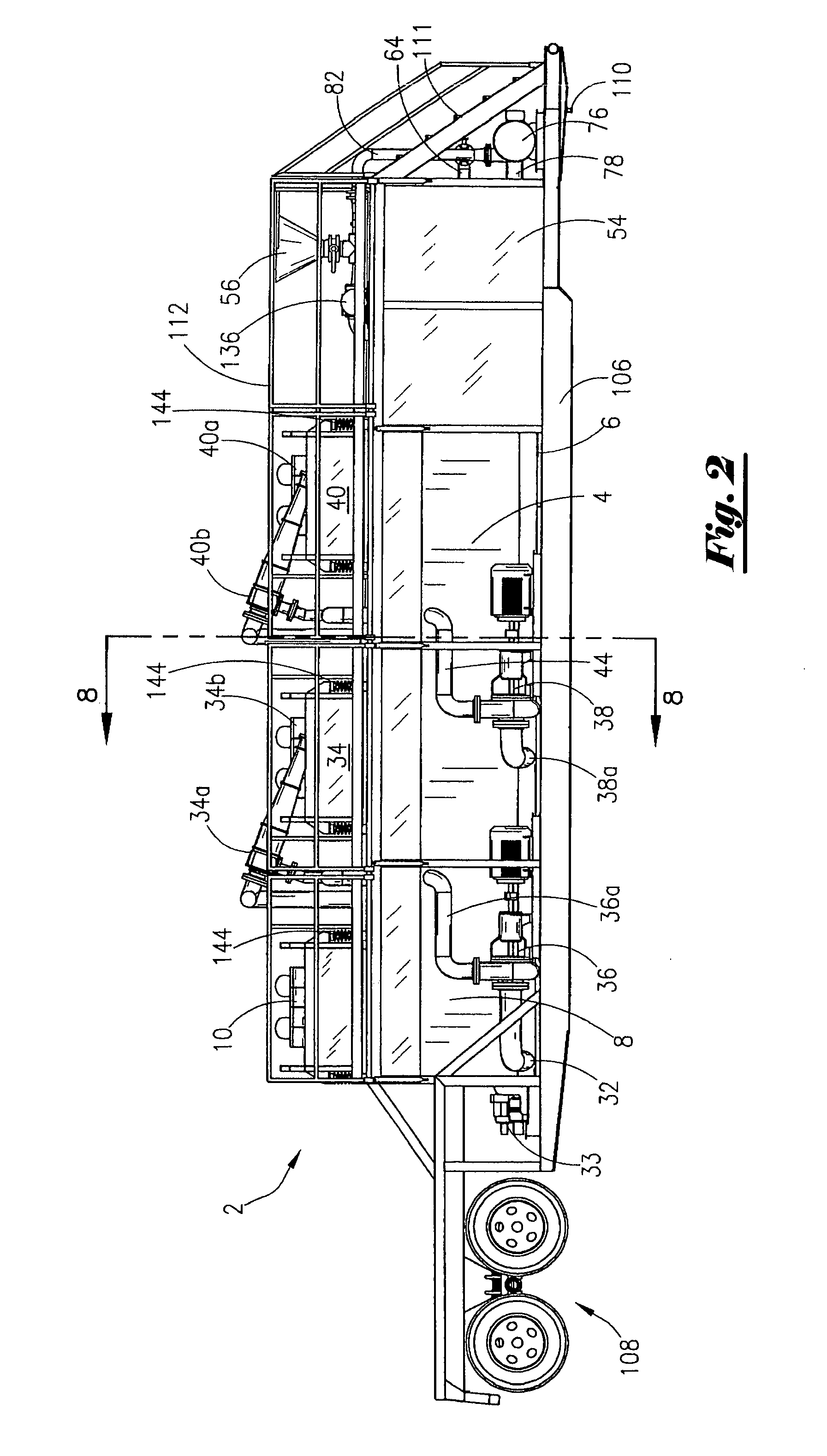
[0014] An advantage of the present invention includes having a modular design wherein a component of the system may be added or removed from the system. Another advantage is the system may be transported easily from one location to another location. For instance, the frame may be lifted via a crane onto vessels, barges, flat beds, etc. Also, the frame may include wheels so that the entire system can be transported via a vehicle such as a truck.
[0015] Another advantage is that the novel system and method will remove solids from five (5) microns and larger in some applications. Still yet another advantage is that the system allows for redundancies in that the fluid stream is introduced to multiple separation devices such as the linear shaker, weir, baffles, cyclone separators, settling tanks, etc. Additionally, the fluid stream can be continuously recycled through the system until the desired level of filtration is achieved.
[0016] Further, it is desirable to have the solids thus collected to be essentially fluid-free. Another advantage is that the solids thus recovered contain very little in-situ fluid.
[0017] A feature of the present invention includes having a linear shaker that separates large diameter solids from the fluid stream. Another feature is the option to use other types of shakers, such as orbital shakers that can also separate small diameter solids from the fluid stream. Yet another feature is the mixing compartment that can be added to the system for the mixing of bulk materials and / or additives to the fluid stream.
[0018] Still yet another feature includes use of an auger type of device for conveying the solids to a pump member. In the preferred embodiment, the auger type of device is a spiral blade without the shaft. The speed of the rotation of the auger blade can be varied depending on the nature of the slurry and the desired process rate of the fluid stream. Thus, a feature includes decreasing or increasing the rotation rate of the spiral blade in order to meet processing rate goals. Another feature includes use of baffles in a baffle module, with the baffle plates being tilted to maximize the impact of the suspended solids during fluid flow as well as to provide the proper orientation for fluid flow through the container.

Problems solved by technology

The fluid being used to drill the well is an expensive, chemically enhanced fluid.
Prior art devices suffer from many deficiencies.
Prior art systems do not allow for adequate separation of solids from the fluid.
The present systems are not packaged in an efficient and well-organized manner.
The prior art systems are bulky and can't be transported from site to site in a single package.

Method used


Image

  • System for separating solids from a fluid stream
  • System for separating solids from a fluid stream
  • System for separating solids from a fluid stream

Examples


Embodiment Construction

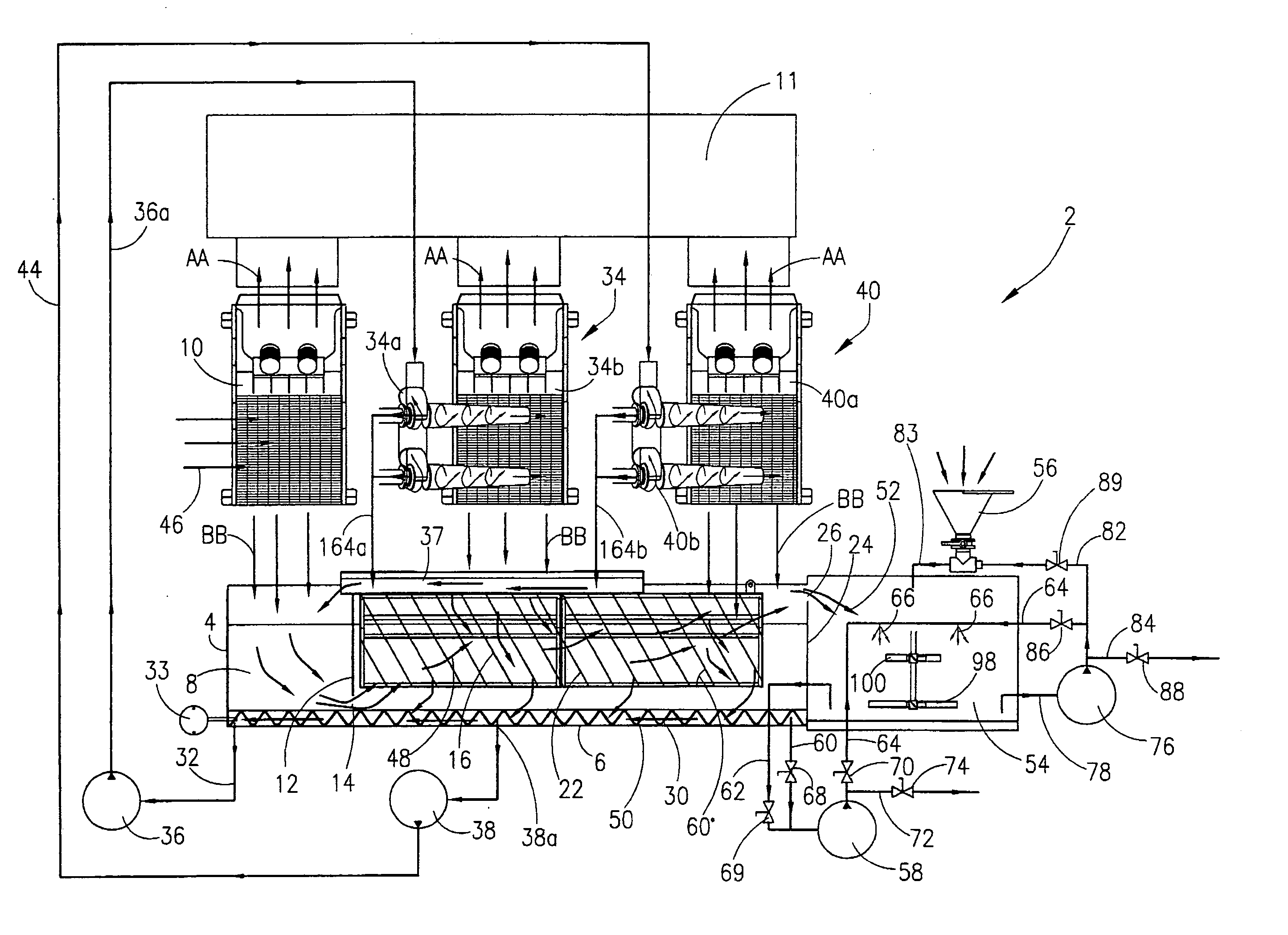
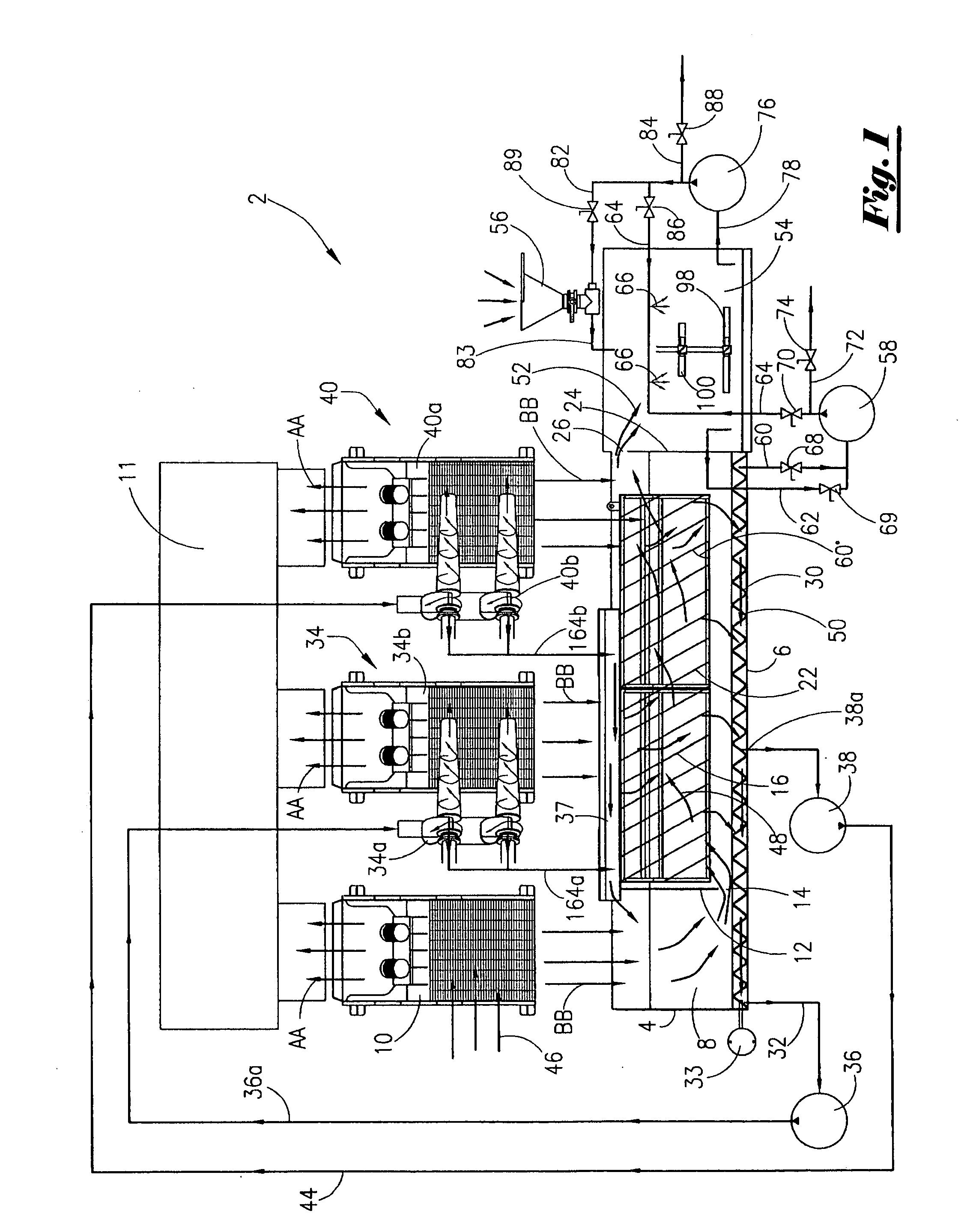
[0029] Referring now to FIG. 1, a schematic diagram of the preferred embodiment of the present invention will now be described. The system 2 seen in FIG. 1 includes a container seen generally at 4. The container 4 has generally a bottom 6, two side walls, an open top, and two end walls. The two side walls and bottom 6 are configured in a “V” bottom shape as is well understood by those of ordinary skill in the art.

[0030] In a first compartment within the container 4, there is contained an initial settling compartment 8. The initial settling compartment 8 has situated above it the linear shaker 10, and wherein the linear shaker originally receives the fluid stream. The linear shaker 10 is commercially available from Fluid Systems, Inc. under the name Linear Shaker. The linear shaker 10 is sometimes referred to as the scalping shaker since it makes the initial cut i.e. initially scalps the fluid stream of solids. It should be noted that the general fluid flow or solids flow through th...


PUM

PropertyMeasurementUnit
angleaaaaaaaaaa
angleaaaaaaaaaa
angleaaaaaaaaaa

Abstract

A system for separating solids from a fluid stream. The system includes a first separator device mounted to a container. The container includes a settling compartment and baffle plate module, with the initial settling compartment receiving the fluid from the first separator device. The fluid stream proceeds through the baffle plate module. The solids within the fluid stream will descend to the bottom of the container. A spiral blade is positioned at the bottom of the container, with the spiral blade adapted to convey solids to a first pump member. The speed of rotation of the spiral blade may be varied. The first pump member discharges the slurry to a second separator device. The second separator device will discharge the separated fluid stream into the baffle plate module. In one embodiment, the first separator device is a linear shaker and the second separator device is a cyclone separator and linear shaker mounted in tandem. The fluid exiting the baffle plate module may be directed into a mixing compartment, with the mixing compartment being part of the container. A method of separating solids from a fluid stream is also disclosed.

Description

[0001] This application is a continuation-in-part of my co-pending application bearing Ser. No. 10 / 288,408, filed on 4 Nov. 2002, which is a division of application Ser. No. 09 / 846,974, filed on 1 May 2001, now U.S. Pat. No. 6,506,310.BACKGROUND OF THE INVENTION [0002] This invention relates to a system for treating fluid streams. More particularly, but not by way of limitation, this invention relates to a system and method for separating solids from a fluid stream. [0003] In industrial applications, a fluid stream may contain solids. The solids may be suspended in solution. The particle sizes may range from larger diameter solids to extremely small diameter solids. As those of ordinary skill in the art will recognize, it is desirable to separate the solids from the fluid. For instance, environmental regulations may require that operators separate the solids from a slurry. Additionally, the operator may wish to reuse the base fluid, and hence, the fluid must be purged of solids. [00...

Claims


Application Information

Patent Timeline
Patent Type & Authority Applications(United States)
IPC IPC(8): B01D21/00
CPCB01D21/0045B01D21/02B01D2221/08B01D21/267B01D21/2461Y10S209/91Y10S209/913Y10S209/92
Inventor KULBETH, ROBERT M.
Owner DEL
Learn More