
Locking-taper abutment for dental implants

Inactive Publication Date: 2005-02-17
HAN BUM KYU
View PDF4 Cites 7 Cited by
  • Summary
  • Abstract
  • Description
  • Claims
  • Application Information

AI Technical Summary

Benefits of technology

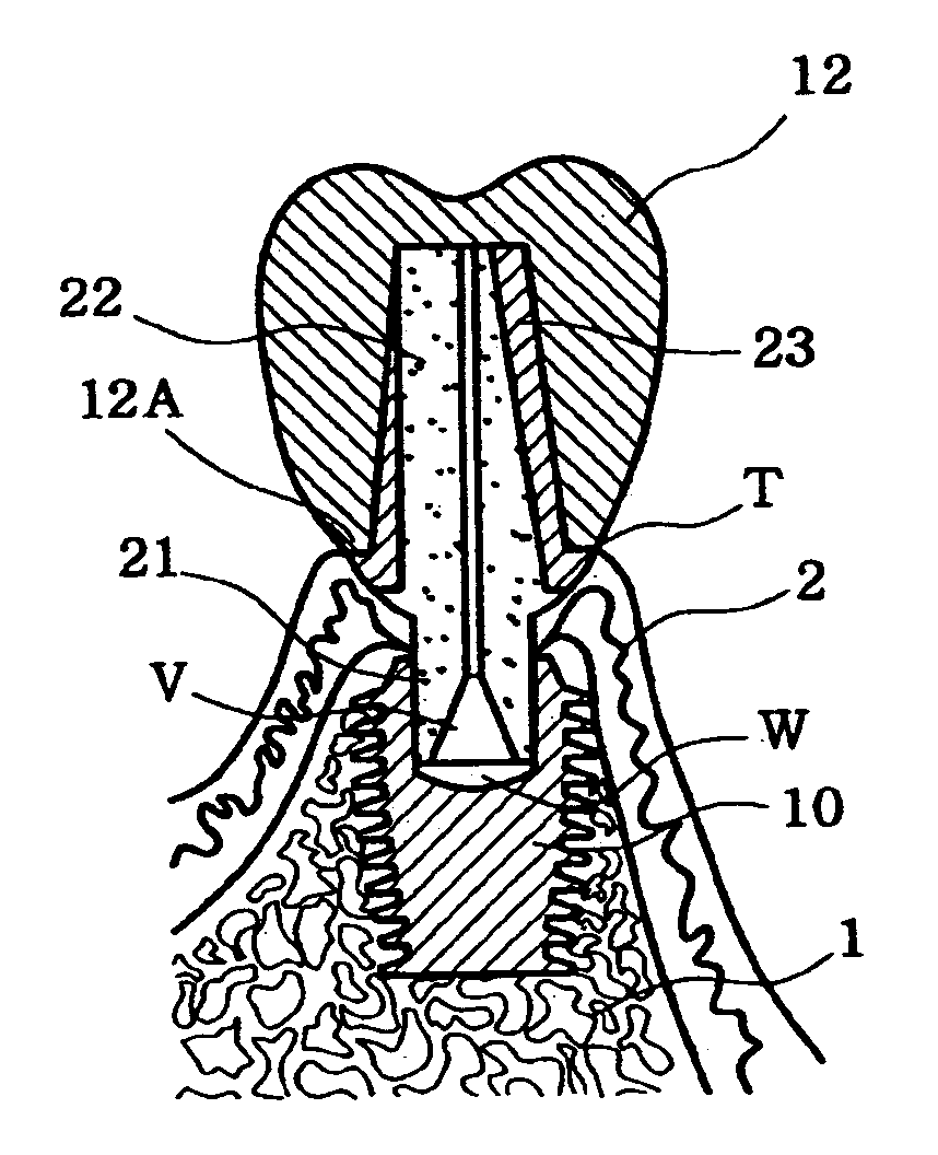
[0020] Accordingly, the present invention has been made keeping in mind the above problems occurring in the prior art, and an object of the present invention is to provide a locking-taper abutment, which is not exposed to the outside, even though a gap exists between a crown margin of an artificial crown and a gingival crest, and in which an elastic force of a lower end of the locking-taper abutment is markedly increased, so that the locking-taper abutment is firmly fastened to a fixture due to the elastic force, and which is easily modified in appearance to simplify a process of manufacturing the artificial crown.
[0024] When the crown bonding layer has a color which is the same as or similar to that of the artificial crown, even though a crown margin, which is the lower end of the artificial crown covering the locking-taper abutment, is placed over the gingival crest, a superior appearance is maintained because the crown bonding layer is exposed to the outside while preventing exposure of the locking-taper abutment to the outside.
[0025] Furthermore, the locking-taper abutment of the present invention has a conical elastic hole which is provided in the lower end of the post part. By the conical elastic hole, the elastic force of the lower end of the post part is increased. Simultaneously, the conical elastic hole increases a space, which is defined between the lower end of the post part and a bottom of a well of the fixture when the locking-taper abutment is coupled to the fixture, thus reducing the compressibility of the air in the space.
[0026] In other words, the lower end of the locking-taper abutment of the present invention has a ring-shaped cross-section due to the conical elastic hole, different from the conventional abutments having circular-shaped cross-sections. Therefore, the lower end of the post part has increased elastic force. Furthermore, the space defined between the post part and the fixture is increased. Thus, when the post part of the locking-taper abutment is inserted into the well of the fixture, the compressibility of the air in the space is reduced, thus reducing a force tending to push the locking-taper abutment outside the well of the fixture.

Problems solved by technology

Once the permanent teeth are damaged by careless maintenance or accident, they are impossible to replace.
However, it is not unusual to lose the permanent teeth by unexpected accidents.
When the permanent teeth are lost, except the wisdom teeth which cause almost no inconvenience when missing, it is not only quite uncomfortable to take in foods but also poor in appearance.
However, the conventional implants have the following two significant problems.
First, in the conventional screw type implants, the abutments may be undesirably moved from the fixtures due to outside impacts and the threaded engagement structure.
Furthermore, because fine gaps exist between the abutments and the fixtures, food remnants may be held in the fine gaps, which can become rotten and thereby cause halitosis, doing damage to neighborhood teeth.
However, in the locking-taper type implants, abutments do not have sufficient surface areas that are in contact with fixtures, thus reducing friction between the fixtures and the abutments.
Therefore, the abutments may be undesirably removed from the fixtures due to impacts transferred from the outside.
Accordingly, the compressed air acts as a force to push out the rod-type post part of the abutment outside the well of the fixture, thus weakening the coupling of the abutment to the fixture.
Furthermore, because the post part of the abutment has a rod-shaped appearance, radial elastic force of the post part is weak.
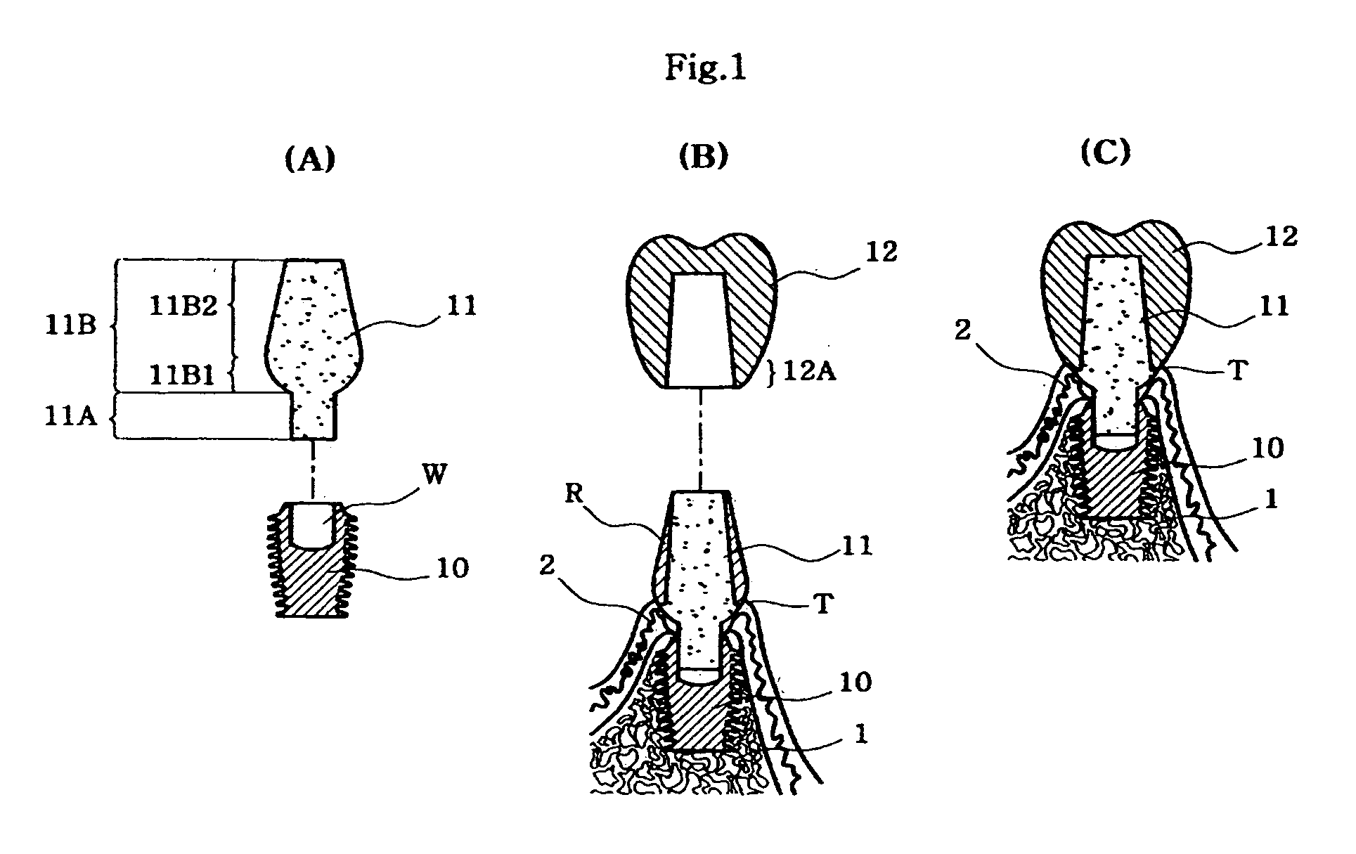
At this time, if the abutment, which is made of metal, is not completely covered by the gingiva, it is somewhat poor in appearance.
Moreover, it is very difficult to remove the bonding agent drawn into the gingivae 2.
Furthermore, the gingivae 2 may be damaged during a process of eliminating the bonding agent drawn into the gingivae 2.
As such, there are the many difficulties in the dental implant operations using the conventional implants.
Furthermore, it is very difficult to polish the outer layer (R) of the body part 11B of the abutment 11, which is made of high-strength metal.

Method used


Image

  • Locking-taper abutment for dental implants
  • Locking-taper abutment for dental implants
  • Locking-taper abutment for dental implants

Examples


Embodiment Construction

[0038] Hereinafter, embodiments of the present invention will be described in detail with reference to the attached drawings.

[0039] Reference now should be made to the drawings, in which the same reference numerals are used throughout the different drawings to designate the same or similar components.

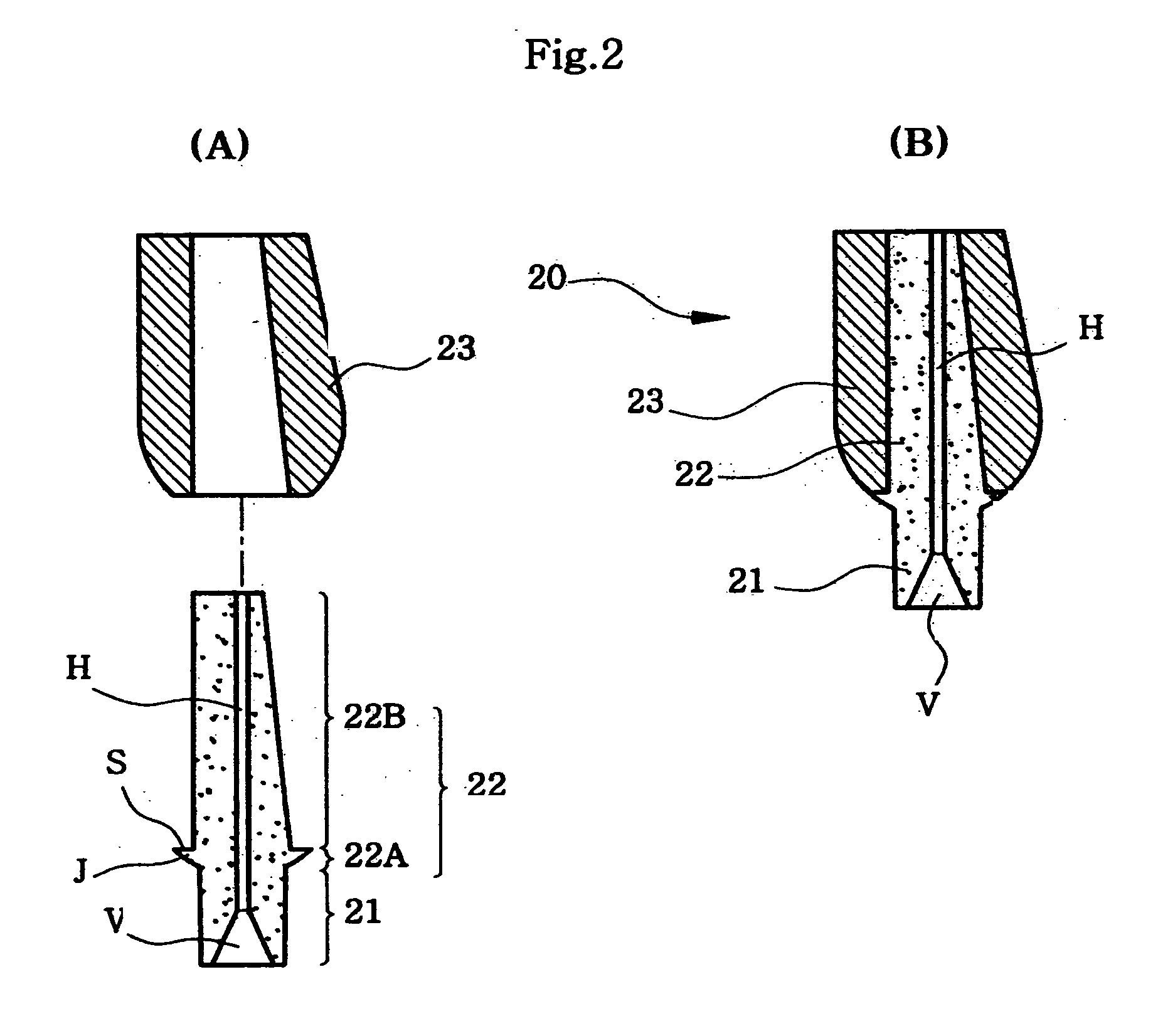
[0040]FIGS. 2A and 2B are sectional views of a locking-taper abutment 20, according to an embodiment of the present invention, wherein: FIG. 2A is an exploded sectional view of the locking-taper abutment 20; and FIG. 2B is a sectional view of the locking-taper abutment 20.

[0041] As shown in FIGS. 2A and 2B, the locking-taper abutment 20 of the present invention includes a post part 21 which is inserted into a well (W) provided in a fixture 10 while enlarging in diameter from the bottom to the top. A conical elastic hole (V) is provided in a lower end of the post part 21.

[0042] The locking-taper abutment 20 further includes a body part 22. The body part 22 has a seating part 22A whic...


PUM


Abstract

The present invention provides a locking-taper abutment which has a crown bonding layer having a good polishing workability and sufficient bonding ability that an artificial crown is firmly supported on the crown bonding layer. The locking-taper abutment includes a post part which is inserted into a well provided in the fixture while enlarging in diameter from bottom to top. The locking-taper abutment further includes a body part. The body part has a seating part extending upwards from the upper portion of the post part exposed to the outside of the well while a diameter of the seating part enlarges from a bottom to a top. The seating part is supported on an inner surface of a gingiva under a gingival crest. The body part further has a vertical part extending upwards from an upper surface of the seating part, with a stopper provided around an outer surface of the upper portion of the seating part. The locking-taper abutment further includes a crown bonding layer covering both the upper surface of the seating part and an outer surface of the vertical part. The locking-taper abutment makes it easy to execute a dental implant operation. Furthermore, The locking-taper abutment prevents an artificial crown bonding agent from flowing into the gingivae.

Description

BACKGROUND OF THE INVENTION [0001] 1. Field of the Invention [0002] The present invention relates generally to abutments for dental implants to make artificial teeth, and more particularly, to a locking-taper abutment which is coupled at a lower end thereof to a fixture of an implant installed in alveolar bone, and has a crown bonding layer which covers an outer surface of an upper portion of the locking-taper abutment, exposed to the outside between inner and outer gingivae, and is made of a resin or acryl that is easily bonded to an artificial crown, so that the locking-taper abutment solves conventional operational difficulties in that, when an artificial crown is bonded and fastened to an outer surface of the abutment, the gingiva must be widened to insert a lower end of the artificial crown into the gingiva for preventing the outer surface of the abutment made of a metal from being exposed to the outside, and the locking-taper abutment prevents excessive bleeding of the gingiva...

Claims


Application Information

Patent Timeline
IPC IPC(8): A61C8/00
CPCA61C8/0069A61C8/005A61C8/0057A61C8/0059A61C8/0071
Inventor HAN, BUM-KYU
Owner HAN BUM KYU
Learn More