Ducument feeder and image reading apparatus with the same

Inactive Publication Date: 2005-02-17
NISCA KK
View PDF8 Cites 11 Cited by
  • Summary
  • Abstract
  • Description
  • Claims
  • Application Information

AI Technical Summary

Benefits of technology

[0014] Accordingly, the entire device is arranged above the platen, and it is easy to mount and dismount the device relative to the platen. An original is transported from the sheet feed stacker and to the discharge stacker along the platen with little damage, and a drive mechanism can be simplified. Further, it is possible to arrange an auxiliary transporting device such as a vacuum chamber for a special original above the transport belt. The original fed from the sheet feed stacker is sucked to the transport belt, thereby reducing friction between the platen and the original and transporting the original reliably.
[0016] According to the present invention, the transporting guide may be disposed between the sheet feed stacker and the transport belt for guiding the original at an angle of 5 to 25 degrees with respect to the platen surface. An angle formed between the discharge stacker and the platen is set to be 30 to 50 degrees. Accordingly, the forward end of the original transported from the sheet feed stacker abuts against the transport belt, and the original is transported to the predetermined location by the transporting force of the belt. Then, the original is peeled off from the platen with a large angle and discharged, thereby feeding and discharging the original more reliably.
[0017] According to the present invention, the transporting guide may be provided at a forward end thereof with an elastic film member contacting the platen surface for urging the forward end of the original toward the transport belt, or an idle roller for nipping the original between the idle roller and the transport belt. Accordingly, particularly in a case that a vacuum fan is provided for sucking the original toward the belt, the original is sucked with the forward end in close contact with the transport belt, so that the original can be transported reliably even with a small sucking force.
[0020] According to the present invention, interconnecting means may be provided for working in conjunction with a rotational motion of the discharge stacker to move the forward end of the sheet feed stacker away from the feeder means. The interconnecting means may be composed of cam means such as an eccentric cam for transmitting the motion of the discharge stacker to the sheet feed stacker, or a gear for transmitting the rotational motion of the discharge stacker to a supporting shaft of the sheet feed stacker. The rear end of the discharge stacker is rotated to widen the space above the sheet feed stacker, so that a bundle of sheets can be placed easily. Also, the forward end of the sheet feed stacker is interconnected and moves away from the feeder means, so that the forward end of the sheet is inserted smoothly and placed in a proper posture.
[0021] According to the present invention, the sheet feed stacker and the transporting means may be arranged in parallel above the platen along the platen, and the discharge stacker may be arranged above the sheet feed stacker in parallel vertically. The transporting means feeds the sheet on the sheet feed stacker along the platen, and is rotated in reverse to discharge the sheet on the platen to the discharge stacker, so that the original is fed and discharged along a substantially linear path without being bent, thereby transporting the originals smoothly under a reduced stress without damage. The transporting means may include an endless belt arranged away from the platen with a small gap and connected to drive means capable of rotating in forward and reverse directions. Also, vacuum means may be provided in the endless belt for sucking the sheet. The vacuum means includes a vacuum chamber covering the belt and a fan for evacuating an inside of the chamber.

Problems solved by technology

In the device, it is difficult to transport a photograph, OHP sheet, and the like through the curved route, i.e. the U-shaped path, without damaging.
The device has a relatively large height over the platen, thereby making the device unstable upon installing and dismounting.
In this case, it is difficult to easily mount and dismount the entire unit above the platen.
When the discharge stacker is disposed above the sheet feed stacker in a small space, it is difficult to set originals on the sheet feed stacker at a proper position.
In the device in which the transporting means, sheet feeding and discharging stackers are arranged above the platen of a scanner, etc., or the sheet feeding and discharging stackers are arranged at a side of the platen, and the originals are transported to the transporting means above the platen, it is still difficult to mount and dismount the device above the platen.
Also, it is difficult to provide a transporting mechanism such as a vacuum fan for a special original such as a photograph above the platen due to a spatial limitation.
Accordingly, when the original is inserted, the original is rubbed and may be damaged.
Especially in a case that the original like a photograph has a surface coated with a soft material such as gelatin, when a bundle of the originals is inserted into the wedge-shaped forward end of the stacker, the originals contact against with each other and may be damaged or the uppermost sheet of the originals is damaged by a paper feed roller.
Therefore, in the device disclosed in Japanese Utility Model Publication (Koukoku) No. 59-7316, in which the space at the rear end of the stacker is widened, it is still difficult to place the originals on the sheet feed stacker at a right position without causing damage.
It is possible that the originals are transported with forward end damaged or bent, thereby causing paper jam.

Method used


Image

  • Ducument feeder and image reading apparatus with the same
  • Ducument feeder and image reading apparatus with the same
  • Ducument feeder and image reading apparatus with the same

Examples


Embodiment Construction

[0038] Hereunder, embodiments of the present invention will be explained with reference to the accompanying drawings. FIGS. 1-5 are views of an image reading apparatus with a document feeding device incorporated therein as a unit.

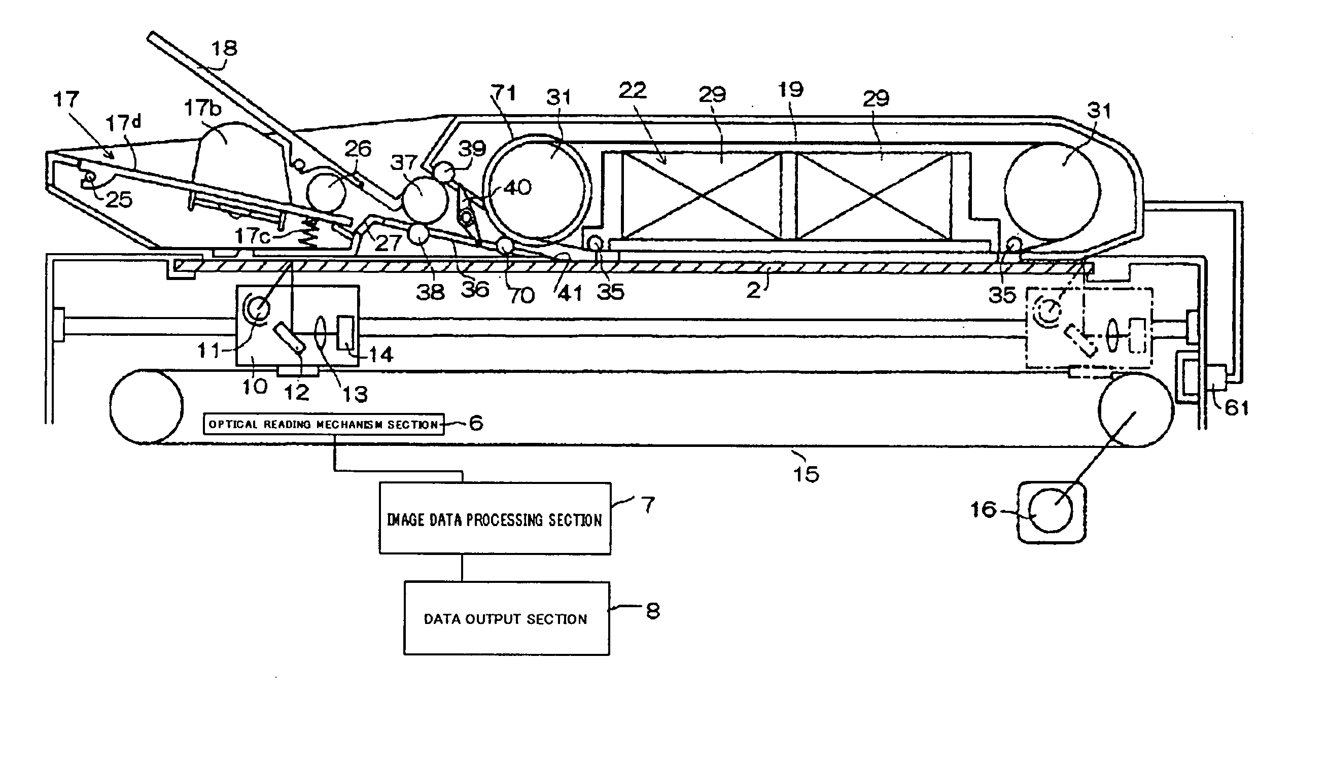
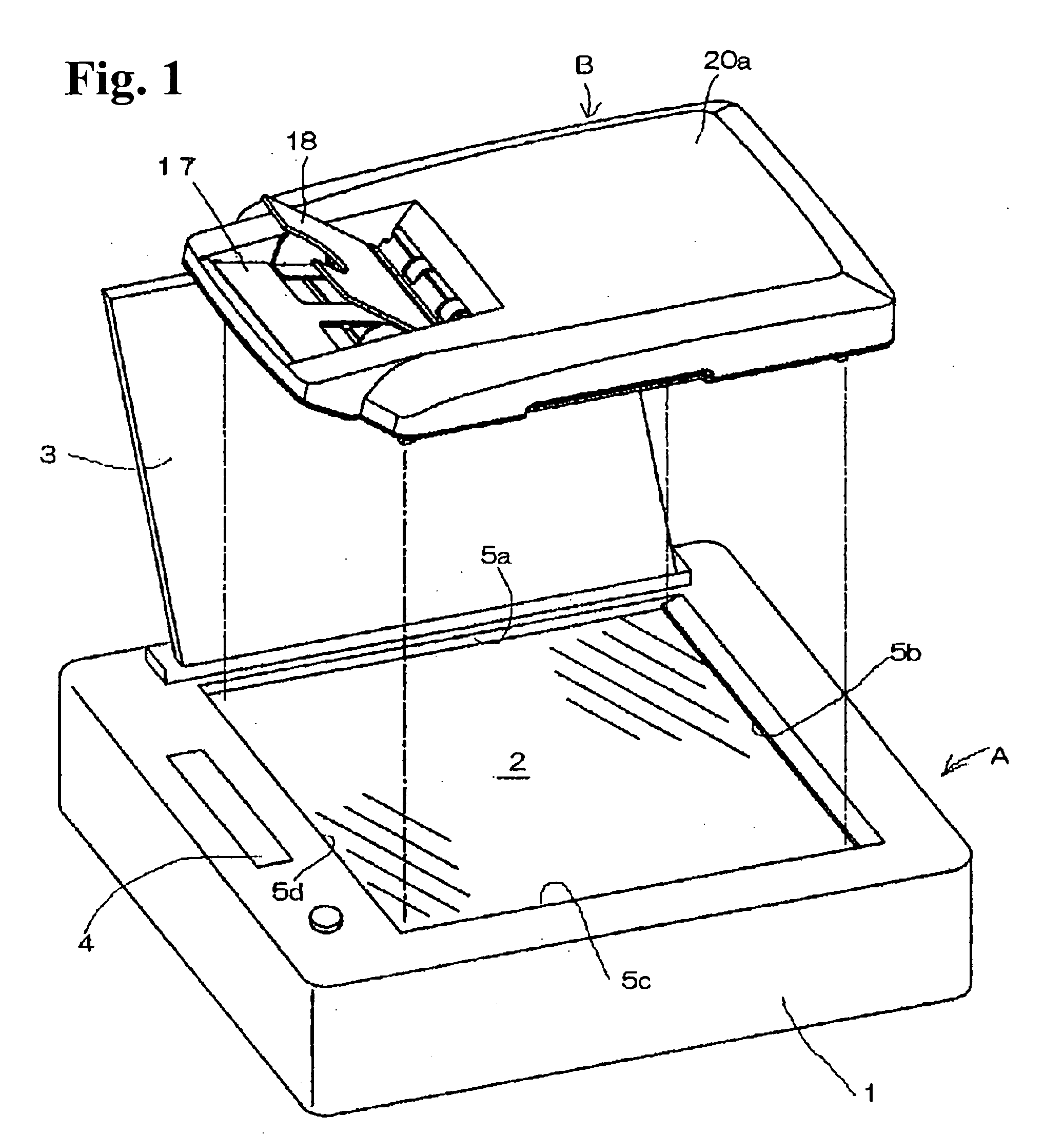
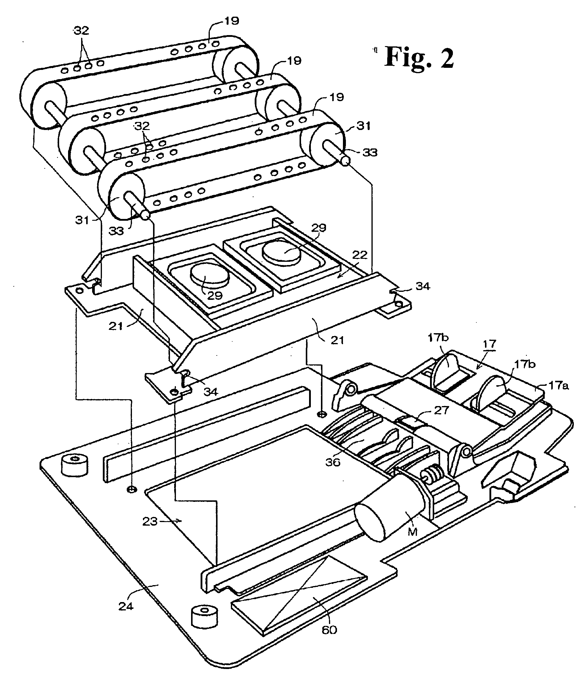
[0039]FIG. 1 is a perspective view showing a condition in which a feeding device B is installed on the image reading apparatus; FIG. 2 is an exploded perspective view of the feeding device; FIG. 3 is a longitudinal cross-sectional view of the feeding device shown in FIG. 2; FIG. 4 is a plane view of the feeding device shown in FIG. 2; and FIG. 5 is an illustration showing a bottom of a transporting unit constituting a part of the feeding device shown in FIG. 2.

[0040] As shown in FIG. 1, a feeding device B is installed above a platen 2 of an image reading apparatus A such as a scanner device. In the image reading apparatus A, the platen 2 is provided on a part of a casing 1. The platen 2 is formed of a transparent and flat glass plate so as to place an ori...


PUM


Abstract

A sheet feeding device includes a sheet feed stacker and a transport belt disposed along a platen substantially horizontally; a discharge stacker disposed above the sheet feed stacker; and a light-shielding cover member provided between the platen and the sheet feed stacker for blocking light from the platen. The entire device is arranged above the platen, and it is easy to mount and dismount the device relative to the platen. An original is transported from the sheet feed stacker and to the discharge stacker along the platen with little damage.

Description

BACKGROUND OF THE INVENTION AND RELATED ART STATEMENT [0001] The present invention relates to a document feeder for feeding an original from a sheet feed stacker to an image reading platen in an image input device such as a copy machine, a printer, a scanner, and a facsimile machine, and storing the originals on a sheet discharge stacker. The present invention also relates to an image reading apparatus with the document feeder. [0002] In general, there have been various feeding devices for automatically feeding and placing an original from a sheet feed stacker to an image reading platen in a scanner. A conventional feeding device is mounted on an upper portion of the platen of the image reading apparatus using the hinge so that the feeding device can be freely opened and closed. When the feeding device is not used for reading an original, an operator opens the feeding device to place the original on the platen manually and then covers the platen with the feeding device. [0003] Recen...

Claims


Application Information

Patent Timeline
IPC IPC(8): B65H1/00B65H5/22B65H31/02H04N1/00H04N1/10
CPCB65H1/00H04N1/1017B65H31/02B65H2405/3322B65H2406/323B65H2801/39H04N1/00567H04N1/00588H04N1/00594H04N1/00602H04N1/0061H04N1/00612H04N1/0062H04N1/00631B65H5/224
Inventor OOMORI, MASAKISHIMIZU, MAKOTOSHIINA, TOSHIHITOISHIMARU, SHUJIJINZA, OSAMU
Owner NISCA KK
Why Eureka
Try Eureka