
Venting arrangement for a vehicle refrigerator and related method

a technology for vehicle refrigerators and venting arrangements, which is applied in the direction of domestic cooling devices, lighting and heating devices, and circulation of cooling fluids, etc. it can solve the problems of time-consuming and laborious, temperature drop in refrigerant, and inability to properly position the exhaust tube assembly relative to the vent opening, so as to reduce the assembly time of the oem, facilitate the adjustment, and enhance the efficiency of the upper vent assembly

Inactive Publication Date: 2005-02-17
NORCOLD
View PDF13 Cites 2 Cited by
  • Summary
  • Abstract
  • Description
  • Claims
  • Application Information

AI Technical Summary

Benefits of technology

[0012] It is an object of the present invention to provide a venting arrangement for a vehicle refrigerator which promotes mixing of the combustion exhaust gases with ventilation air prior to exiting the vent in a space located away from the refrigerator components through the use of a flue exhaust tube assembly.
[0021] It is another object of the present invention to provide a venting arrangement for a vehicle refrigerator that increases airflow over the back of the refrigerator through reduced resistance and increased chimney effect.

Problems solved by technology

The refrigerant vapor expands in the evaporator which causes a temperature drop in the refrigerant.
While both conventional methods for ventilation of the combustion exhaust gases have been proven to be acceptable for their intended uses, both are associated with limitations.
In the first method, proper positioning of the exhaust tube assembly relative to the vent openings is time consuming.
Extending the flue tube through an independent hole in the wall is even further time consuming.
The resultant mixture is warmer and therefore less efficient for cooling the absorber and condenser of the refrigerator's cooling unit.

Method used


Image

  • Venting arrangement for a vehicle refrigerator and related method
  • Venting arrangement for a vehicle refrigerator and related method
  • Venting arrangement for a vehicle refrigerator and related method

Examples


Embodiment Construction

[0028] The following description of the preferred embodiments of the present invention is merely exemplary in nature and is in no way intended to limit the invention, its application, or uses.

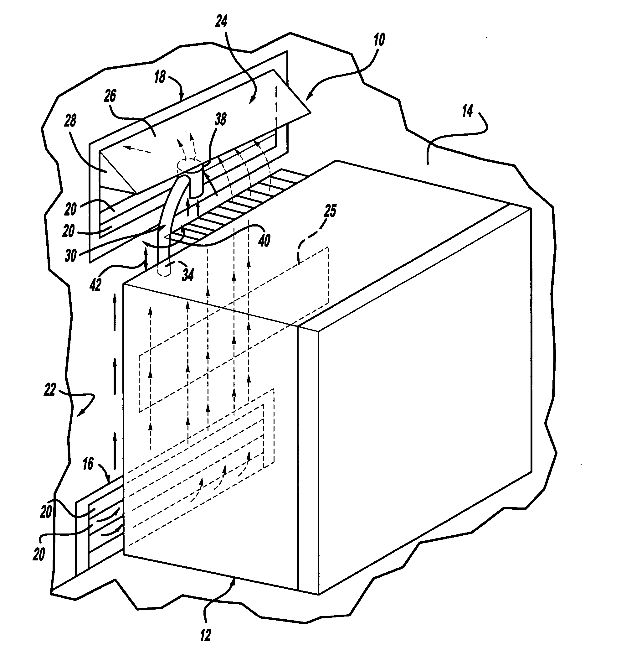
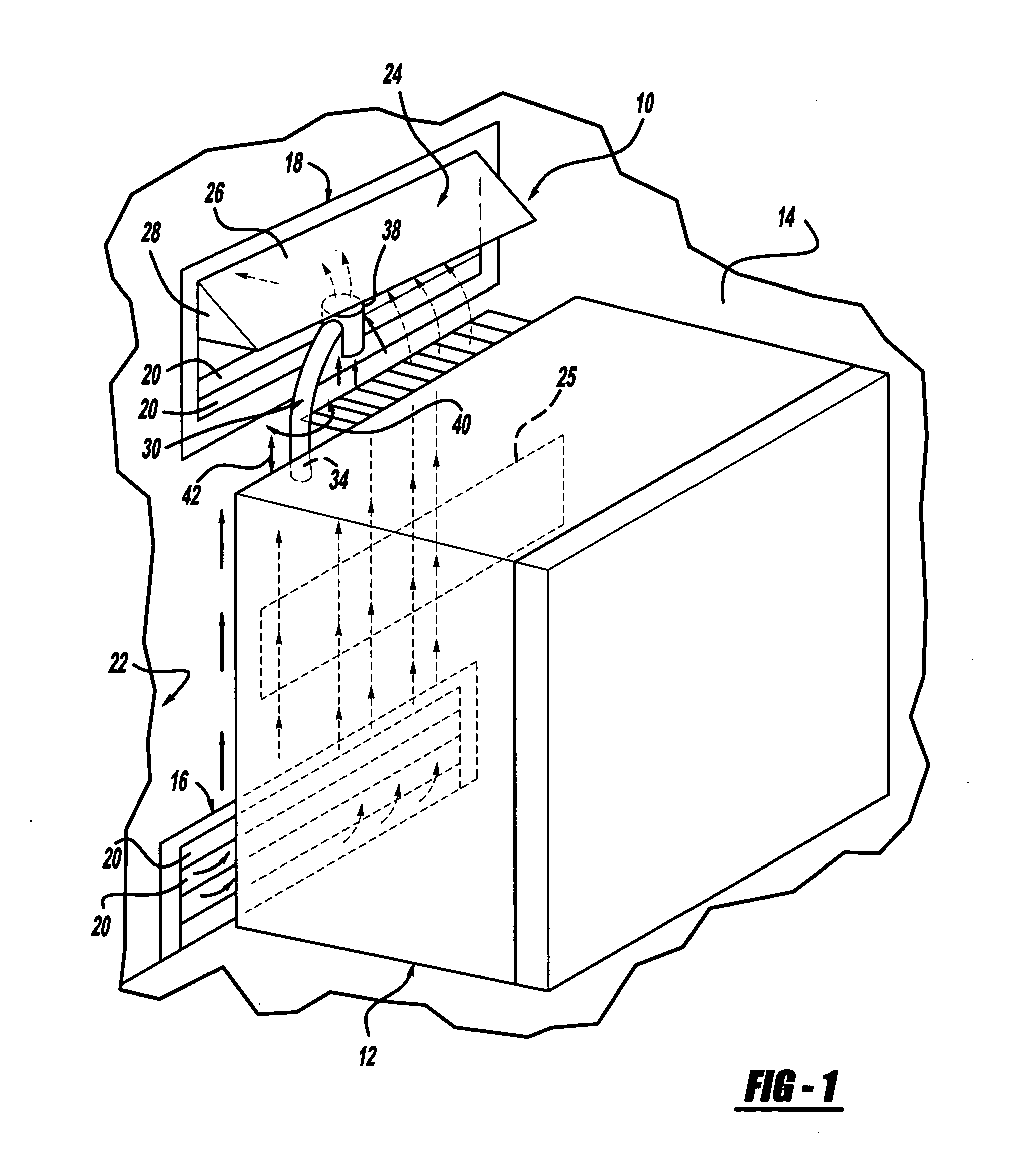
[0029] Referring initially to FIG. 1, a venting arrangement for a vehicle refrigerator constructed in accordance with the teachings of the present invention is illustrated and generally identified at reference number 10. The venting arrangement 10 is shown operatively associated with a vehicle refrigerator 12 that is conventionally installed within a vehicle 14. In the exemplary arrangement illustrated, the vehicle is a recreational vehicle 14. It will become apparent to those skilled in the art, however, that the teachings of the present invention are not so limited. In this regard, the teachings of the present invention have application for any vehicle incorporating a refrigerator requiring the discharge of flue gases.

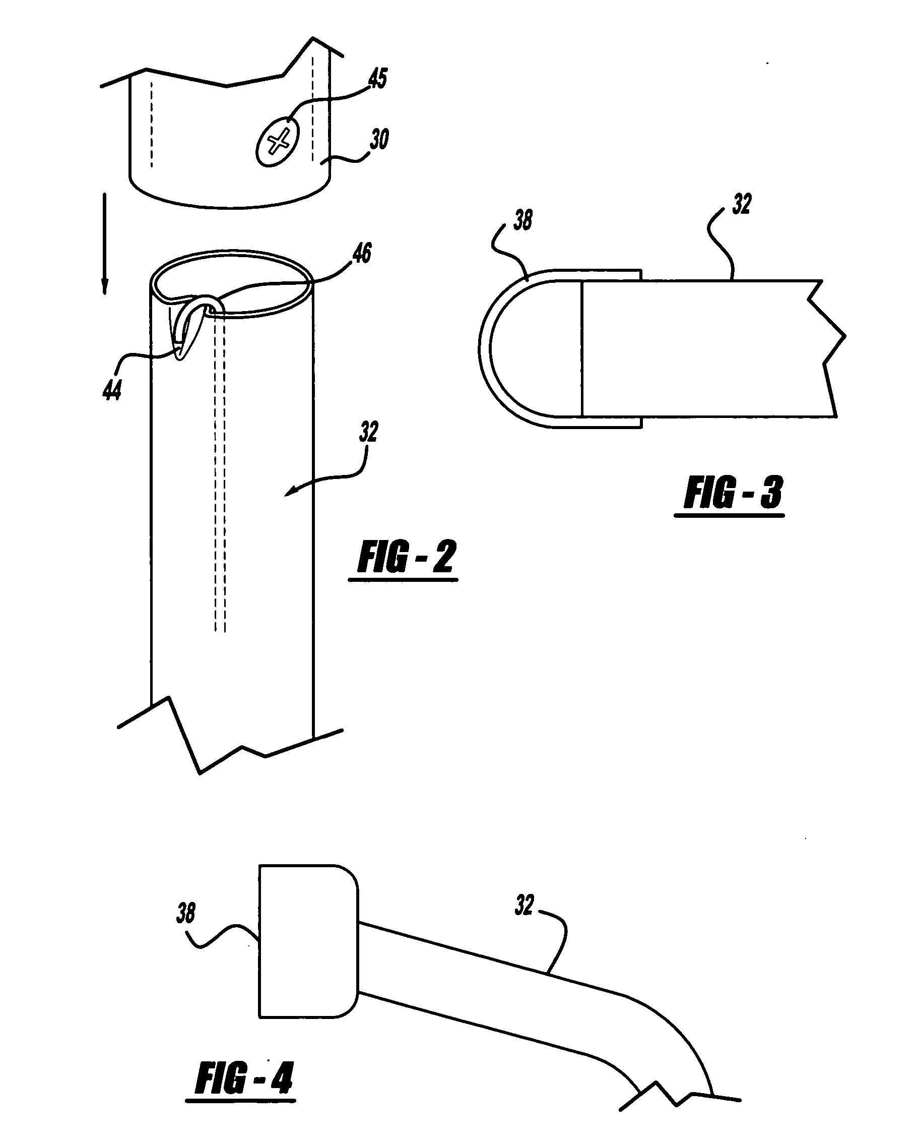
[0030] With continued reference to FIG. 1 and additional reference to FIG...


PUM


Abstract

A venting arrangement for a vehicle refrigerator including a lower vent assembly and an upper vent assembly. The lower vent assembly provides ventilation intake for cooling of refrigeration components. The upper vent assembly provides ventilation exhaust for cooling of refrigeration components. The venting arrangement further includes a flue exhaust tube assembly. The flue exhaust tube assembly causes the combustion exhaust gases to mix with the ventilation air prior to being exhausted near the upper vent assembly and away from the refrigerator components.

Description

CROSS-REFERENCE TO RELATED APPLICATIONS [0001] This application claims the benefit of U.S. Provisional Application No. 60 / 456,703, filed on Mar. 21, 2003. The disclosure of the above application is incorporated herein by reference.FIELD OF THE INVENTION [0002] The present invention generally relates to vehicle refrigerators. More particularly, the present invention relates to a venting arrangement for a vehicle refrigerator. BACKGROUND OF THE INVENTION [0003] Vehicles, including but not limited to recreational vehicles (“RVs” in the United States and “Caravans” in Europe), tractor trailers, airplanes, boats, trains, and the like, often incorporate refrigerators for the comfort and convenience of the occupants. These refrigerators are usually absorption-type refrigerators. [0004] An absorption refrigerator includes a heat generator for heating a solution of refrigerant and an absorbent. Heat releases the refrigerant from the absorbent to form a high pressure refrigerant vapor. The re...

Claims


Application Information

Patent Timeline
Patent Type & Authority Applications(United States)
IPC IPC(8): F25D11/02F25D23/00
CPCF23J2213/203F23L17/02F25B2333/003F25D2323/00272F25D23/003F25D2323/00261F25D11/027
Inventor LEEUWEN, J. H. VAN
Owner NORCOLD
Learn More