
Process for position indication

a position indication and processing technology, applied in the direction of transducer details, electrical transducers, electrical apparatus, etc., can solve the problems of frequency dependent errors, voice coil transducers become very distorting, and reduce the effectiveness of other corrections

Inactive Publication Date: 2005-02-10
TYMPHANY HK
View PDF14 Cites 142 Cited by
  • Summary
  • Abstract
  • Description
  • Claims
  • Application Information

AI Technical Summary

Benefits of technology

In one embodiment of the present invention, a control process is provided for an actuator. The process comprises calibrating an actuator control parameter with respect to a generalized coordinate and using a value of the generalized coordinate to control the actuator. In one embodiment, the generalized coordinate comprises a...

Problems solved by technology

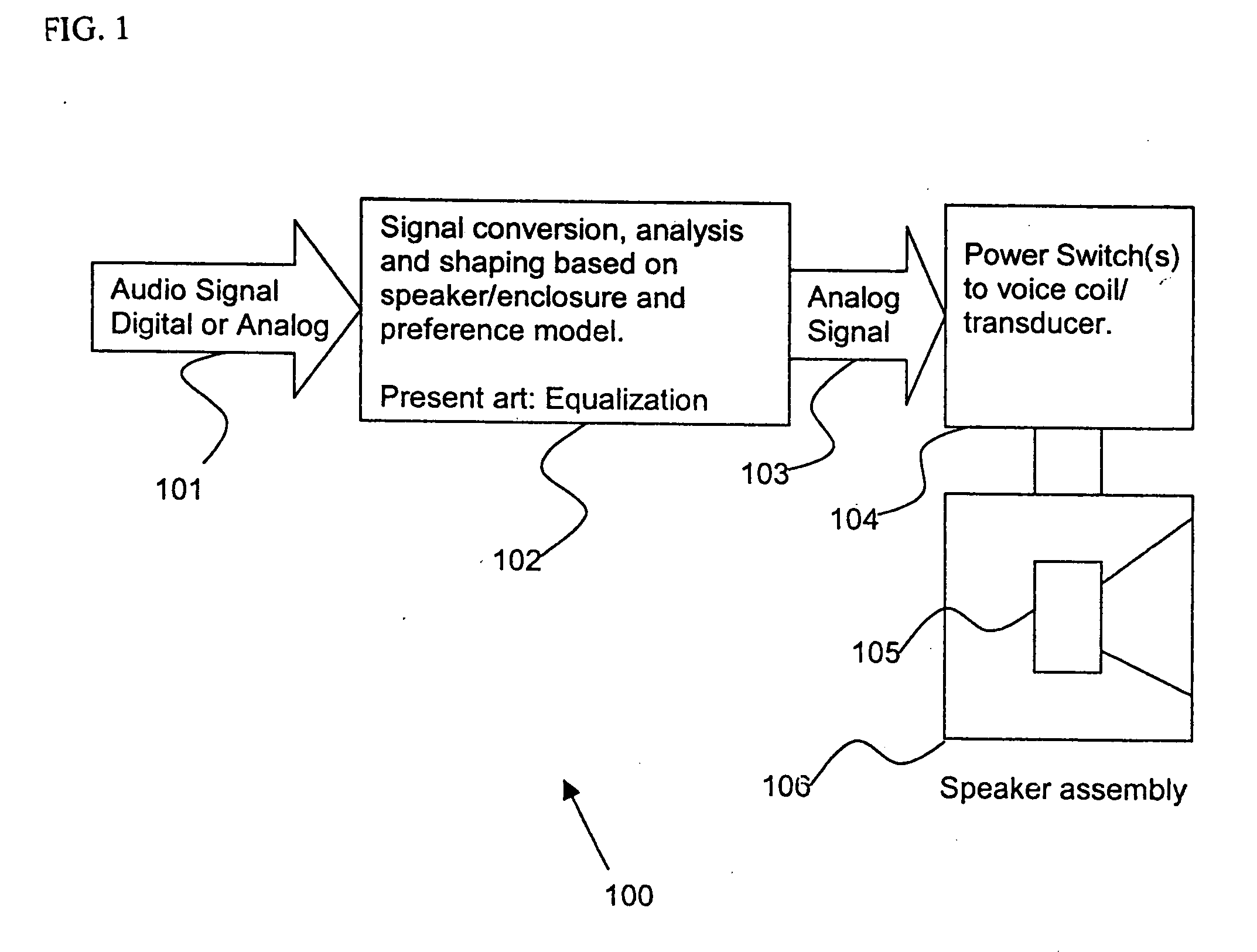
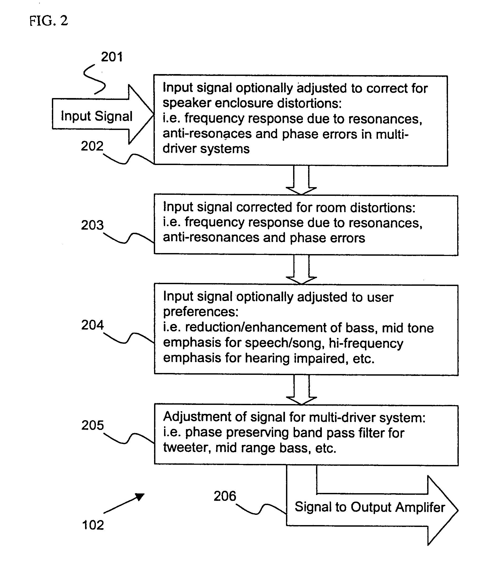
A problem with the foregoing system is that there are frequency dependent errors as well as phase dependent errors which are not corrected, as well as errors due to the non-linear distortion of the transducer which reduce the effectiveness of the other corrections.
There are a number of causes of audio distortion which involve the structure and operation of the voice coil transducer 300.
At high signal levels, voice coil transducers become very distorting.
This distortion is largely caused by the nonlinearities in the coil motor factor, in the restoring force of the coil / diaphragm assembly suspension, and the impedance of the coil.
Nonlinearities in the motor factor in a voice coil transducer result from the fact that the coil and the region of uniform static magnetic field are limited in size, coupled with the fact that the coil moves relative to the static field.
The actual size of the static magnetic field region, and its size relative to the voice coil, represent engineering and economic compromises.
As the audio signal increases in magnitude, the coil tends to move away from the region of maximal static magnetic field, and the motor factor decreases, thus effecting a less uniform coil movement and distorting the sound wave.
Although approximations can be made, it difficult to predict the response of a system under all conditions, and thus to create a robust control system.
Further nonlinearities arise due to other electrodynamical effects caused by the application of the audio signal to the transducer voice-coil.
However, the resulting coil current varies both out of phase and nonlinearly with this voltage.
Nevertheless, none of these prior techniques appear to have made any significant impact on commercial audio practice.
However, problems with noise and stability have prevented these systems from being widely used.
In order to be effective, however, this and similar methods require several factors that are not easily provided.
Thirdly, a high-speed control loop is required for accurate compensation of even quite low-frequency distortions, imposing considerable constraints on the estimation algorithms.
Fourth, positional information is not easily obtainable from standard sensors such as microphones and accelerometers, because these sensors measure motional variables such as coil / diaphragm velocity or acceleration, and the integration of motional variables to estimate position is fraught with systematic errors due to changing average offsets of the coil / diaphragm from its no-drive equilibrium position.
None of the above methods have been shown to lead to a successful approach and, ipso facto, none of these methods has made a significant difference to the commercial art.
Some of the issues can be addressed by improving the circuitry through digital means; but even with the digital circuitry to handle the signal shaping, the transducer itself has significant nonlinearities that can never be addressed adequately by shaping the input signal to the transducer.

Method used


Image

  • Process for position indication
  • Process for position indication
  • Process for position indication

Examples


Embodiment Construction

)

Detailed Description 1

System

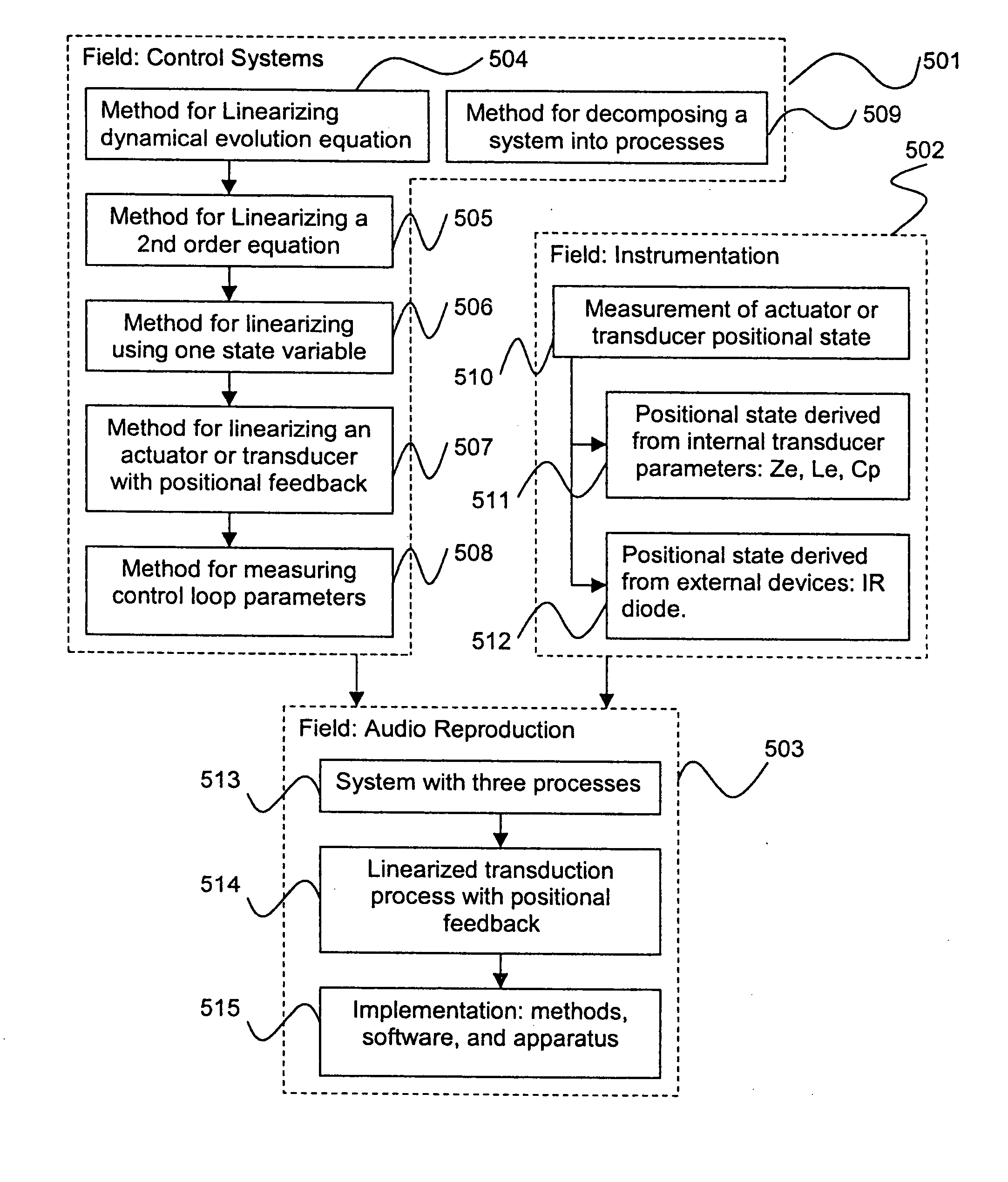
Many control engineering problems require input from several fields: mathematics, physics, systems engineering, electronic engineering, and, for this disclosure, acoustics. There are a number of key concepts developed in these different fields that were required to produce the final embodiment. The relationships between the main areas of invention are illustrated in FIG. 5. To assist understanding, the areas of invention have been grouped under three different headings: control systems engineering 501, instrumentation 502 and audio reproduction 503. FIG. 5 shows how the concepts and inventions in control engineering 501 and instrumentation 502 are linked to audio reproduction 503, and how the inventions have been reduced to practice using the audio reproduction field.

An enabling invention in the area of control engineering501 was the linearization method for dynamical equations 504 used in modeling physical systems to be controlled, such as actuator...


PUM


Abstract

Control system for devices such as an audio reproduction system, an actuator device, an electromechanical device and a telephony device. The system includes control circuitry which receives an input signal and a signal indicative of a position of a portion of the controlled apparatus. The control circuit provides an output signal to the controlled apparatus to affect an operation of the controlled apparatus. The output signal provides control of the apparatus to compensate for one or more of: motor factor; spring factor; back electromotive force; and impedance of a coil in a driver of the controlled apparatus. The signal indicative of position is derived by one or more position indicator techniques such as an infrared LED and PIN diode combination, position dependent capacitance of one portion of the controlled apparatus with respect to another portion of the controlled apparatus, and impedance of a coil in the controlled apparatus. The control circuitry is configurable to control transconductance and / or transduction of the system being controlled. A technique is disclosed to detect and measure a cant of a voice coil transducer, the technique including measuring a capacitance between one portion of the voice coil transducer with respect to another portion of the voice coil transducer over a range of movement of the voice coil during operation.

Description

COMPUTER PROGRAM LISTING APPENDIX The computer program listing appendix attached hereto consists of two (2) identical compact disks, copy 1 and copy 2, each containing a listing of the software code for embodiments of components of this invention. Each compact disk contains the following files (date and time of creation, size in bytes, filename): Directory of D:\May 30, 200309:09 AM 1,1880711115B.txtMay 30, 200309:11 AM 7,6710711115C.txtMay 30, 200309:12 AM 1,0210711115D.txtMay 30, 200309:18 AM 1,3610711115E.txtMay 30, 200309:19 AM  3350711115F.txtMay 30, 200309:20 AM  6490711115G.txtMay 30, 200309:08 AM 3,989071115A.txtMay 30, 200309:05 AM38,253071119.txt8 File(s)54,467 bytes0 Dir(s)   0 bytes free The contents of the compact disk are a part of the present disclosure, and are incorporated by reference herein in their entireties. COPYRIGHT NOTICE A portion of the disclosure of this patent document contains material that is subject to copyright protection. The copyright owner has ...

Claims


Application Information

Patent Timeline
IPC IPC(8): H04R3/00H04R29/00
CPCH04R29/003
Inventor BROWNING, RAYMONDANWAR, GEORGEBEN-MENAHEM, SHAHARJABBARI, ALILESKE, LAWRENCE A.MEDIN, DAVIDMESIWALA, HAKIM M.
Owner TYMPHANY HK
Learn More