
Optical information recording medium, an optical information recording apparatus, an information processing apparatus, program and information recording method

a technology of optical information and recording medium, applied in the field of information recording techniques, can solve the problems of increasing motor cost, increasing sound and vibration or difficulty in servo system design, and difficult to rotate the optical disc at such a high speed, and achieve the effect of stable recording quality and stable recording quality

Active Publication Date: 2005-02-10
RICOH KK
View PDF12 Cites 21 Cited by
  • Summary
  • Abstract
  • Description
  • Claims
  • Application Information

AI Technical Summary

Benefits of technology

[0013] It is a general object of the present invention to provide an improved and useful optical information recording apparatus in which the above-mentioned problems are eliminated.
[0014] A more specific object of the present invention is to provide an optical information recording apparatus which can maintain a stable recording quality when recording information on an optical information recording medium having a recording layer of a multilayer structure according to a constant linear velocity method.
[0015] Another object of the present invention is to provide an optical information recording apparatus which can maintain a stable recording quality when recording information on an optical information recording medium having a recording layer of a multilayer structure according to a constant angular velocity method.

Problems solved by technology

On the other hand, according to the CLV method, it is necessary to increase a rotation speed of an optical disc as a recording point goes inner side of the optical disc, which makes it difficult to rotate the optical disc at such a high speed.
Moreover, an increase in the rotation speed of the optical disc may cause a problem of increasing motor cost, increasing sound and vibration or difficulty in servo system design.
However, a recording capacity achieved by the CAV method is smaller than that of the CLV method.
However, even if a recoding is performed according to the ZCLV method, when attempting a higher recording speed, there is a limitation in an output power of a semiconductor laser as a light source used in an optical disc drive unit.
In the meantime, there is a problem mentioned below when performing a recording on a multilayer optical disc having a recording layer containing a plurality of layers.
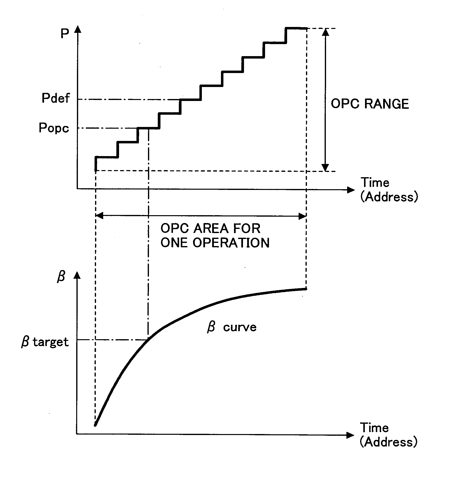
Accordingly, there is a problem in that an optimum recording power acquired by OPC is changed due to changes in the amount of the light beam.
Such a fluctuation in the optimum recording power may be a cause of degradation of recording characteristic such as a jitter or an error rate of the second recording layer.

Method used


Image

  • Optical information recording medium, an optical information recording apparatus, an information processing apparatus, program and information recording method
  • Optical information recording medium, an optical information recording apparatus, an information processing apparatus, program and information recording method
  • Optical information recording medium, an optical information recording apparatus, an information processing apparatus, program and information recording method

Examples


first embodiment

[0037] A description will now be given, with reference to FIG. 1 through FIG. 5, of the present invention.

[0038] An optical information recording apparatus according to the first embodiment of the present invention records information on an optical disc, which is a multilayer optical disc having two record layers layers as a recordable rotation-type optical information recording medium.

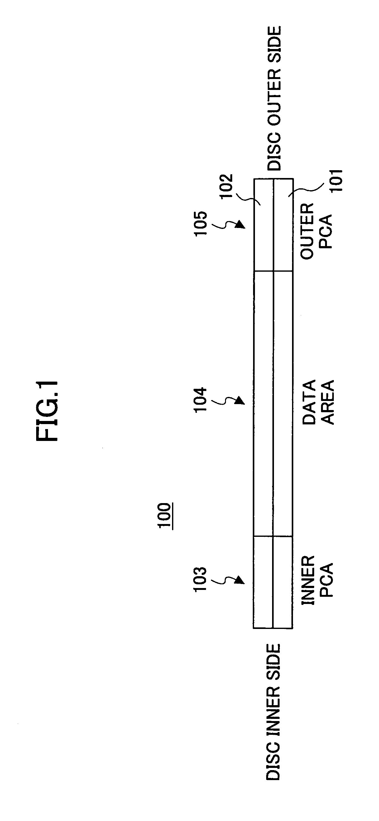
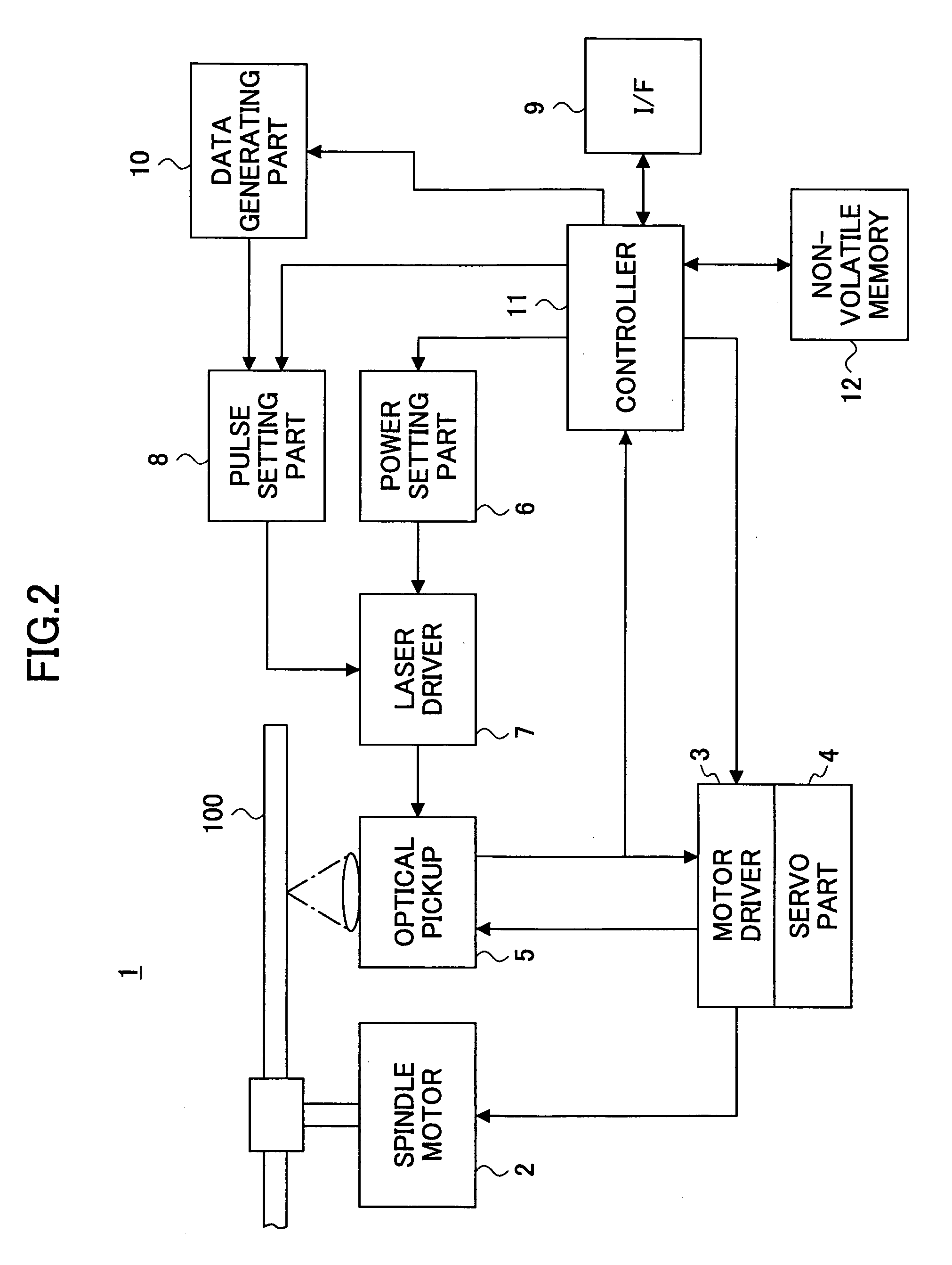
[0039]FIG. 1 is an illustration showing an area structure of an optical disc 100 according to the first embodiment of the present invention. As shown in FIG. 1, the optical disc 100 has a two-layer structure, which comprises a recording layer (first layer) 101 located on a side of an optical pickup 5 (refer to FIG. 2) mentioned later and a recording layer (second layer) 102. The optical disc 100 is a dye-type medium which uses an organic color dye material. FIG. 1 shows a cross-sectional view of the optical disc 100 taken along a radial direction. The optical disc 100 has an inner PCA 103, an informa...


PUM

PropertyMeasurementUnit
areaaaaaaaaaaa
poweraaaaaaaaaa
constant linear velocity methodaaaaaaaaaa

Abstract

An optical information recording apparatus can maintain a stable recording quality when recording information on an optical information recording medium having a recording layer of a multilayer structure. An optical information recording medium of a rotating type has a plurality of recording layers each having an information recording area in which information is recorded using a laser beam. An inner power calibration area is provided in each of the recording layers at a location closer to a center of rotation of the optical information recording medium than the information recording area, and is used to perform a test write in an optimum power control process to acquire an optimum recording power of the laser beam. The outer power calibration area is provided at a location farther from the center of rotation than the information recording area, and is used to perform a test write in an optimum power control process to acquire an optimum recording power of the laser beam.

Description

CROSS-REFERENCE TO RELATED APPLICATION [0001] This application is a U.S. continuation application filed under 35 U.S.C. 111(a) claiming benefit under 35 U.S.C. 120 and 365(c) of PCT application JP2004 / 003938, filed Mar. 23, 2004.BACKGROUND OF THE INVENTION [0002] 1. Field of the Invention [0003] The present invention generally relates to information recording techniques and, more particularly, to an optical information recording technique for recording information on an optical information recording medium having a multi-layer recording layer that contains an information recording area. [0004] 2. Description of the Related Art [0005] In recent years, with improvement in their functions, personal computers (hereinafter, may be abbreviated as PCs) have become capable of handling audio-visual (AV) information such as music information or image information. Since an amount of the AV information is extremely large, optical discs such as CD (Compact Disc) or DVD (Digital Versatile Disc) h...

Claims


Application Information

Patent Timeline
Patent Type & Authority Applications(United States)
IPC IPC(8): G11B7/00G11B7/0045G11B7/007G11B7/125G11B7/1267G11B7/24
CPCG11B7/00736G11B2007/0013G11B7/1267
Inventor NINOMIYA, MASAKI
Owner RICOH KK
Learn More