
Inter-vehicle communication method and device

a communication method and vehicle technology, applied in the direction of navigation instruments, instruments, electric signalling details, etc., can solve the problems of hardly any other information to be transmitted, increased communication load, and one-to-one communication, and achieve the effect of reducing the number of calls

Active Publication Date: 2005-02-10
ALPINE ELECTRONICS INC
View PDF6 Cites 72 Cited by
  • Summary
  • Abstract
  • Description
  • Claims
  • Application Information

AI Technical Summary

Benefits of technology

The present invention aims to reduce the number of calls and traffic volume, and allow data to be relayed in a wide area.

Problems solved by technology

The technical problem addressed in this patent text is how to improve inter-vehicle communication by increasing the communication area and reducing the traffic volume, while preventing an increase in the bandwidth used for information transmission.

Method used


Image

  • Inter-vehicle communication method and device
  • Inter-vehicle communication method and device
  • Inter-vehicle communication method and device

Examples


Embodiment Construction

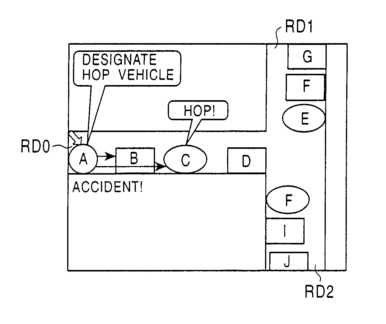
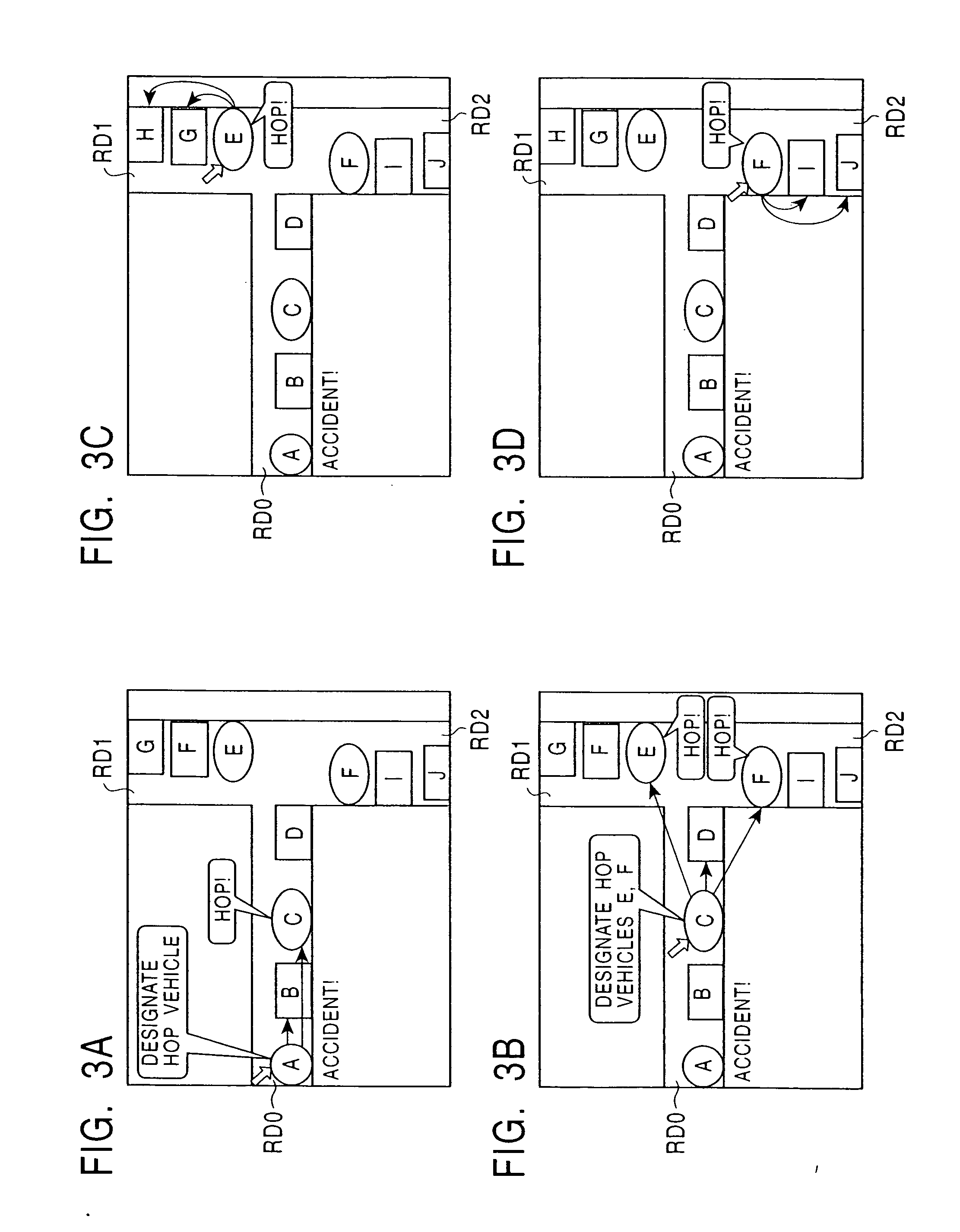
[0025] The present invention improves the communication load by designating a vehicle through which information hops (in other words, a vehicle relaying information) and broadcasting the information in a case where a plurality of vehicles exists in a communication area.

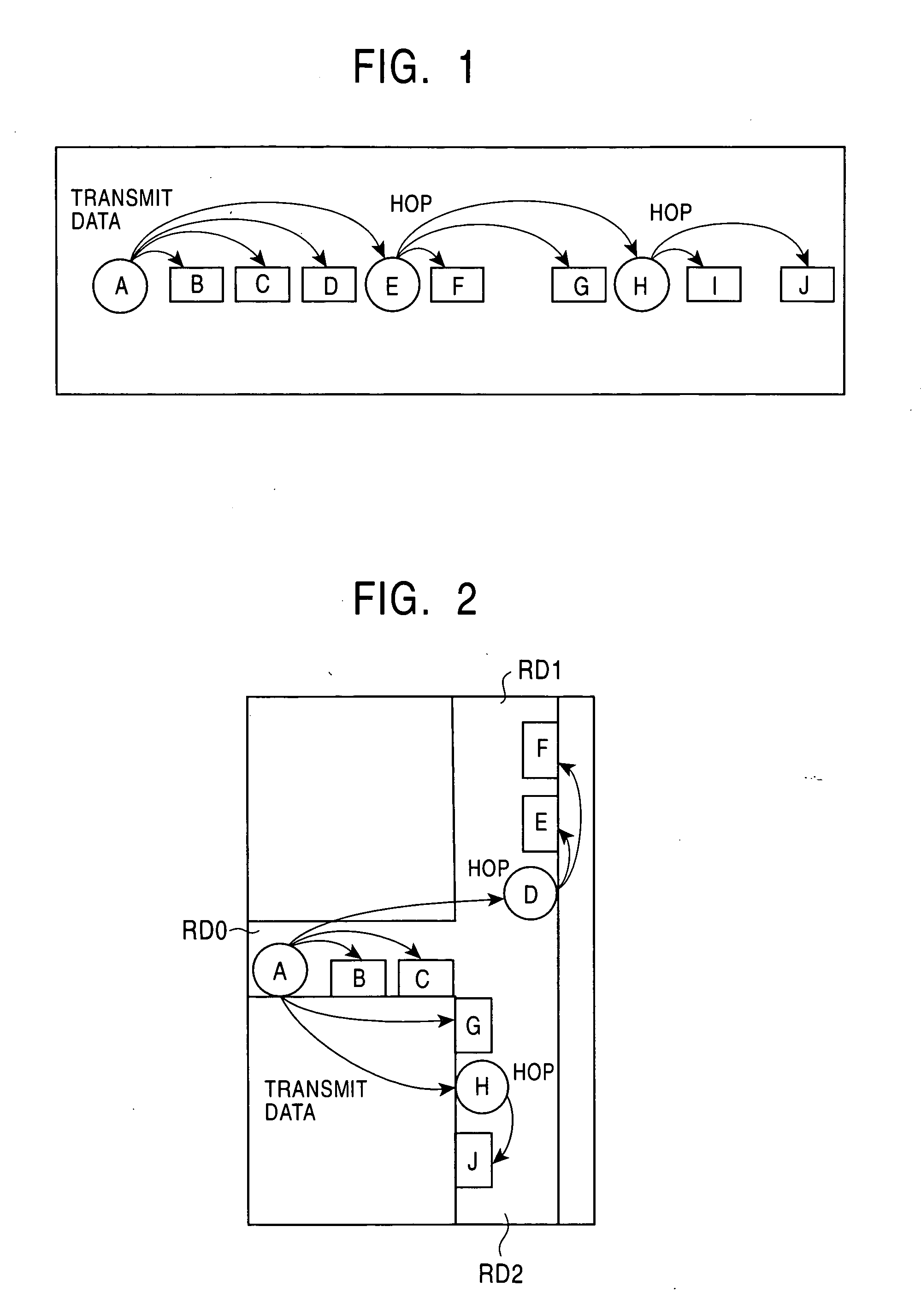
[0026]FIG. 1 is an explanatory diagram schematically showing the present invention. When a vehicle A transmits transmission information, such as accident occurrence information, to its peripheral vehicles, the vehicle A designates a relay vehicle E and broadcasts the transmission information to peripheral vehicles B through E. Also, when the relay vehicle E transmits reception information to its peripheral vehicles, the relay vehicle E designates a relay vehicle H and broadcasts transmission information to vehicles F through H (the information hops). The relay vehicle H also relays information (the information hops).

[0027]FIG. 2 is an explanatory diagram showing a method for determining a relay vehicle.

[0028] Each ...


PUM


Abstract

An inter-vehicle communication method according to the present invention performs communication by sequentially relaying transmission information among vehicles. For broadcasting the transmission information to peripheral vehicles, a vehicle transmitting the transmission information designates relay vehicles and causes the relay vehicles to broadcast reception information to peripheral vehicles of the relay vehicles. In order to designate the relay vehicles, the vehicle transmitting the transmission information receives positional information from its peripheral vehicles, identifies branch roads on which the respective peripheral vehicles exist by referring to map information, and designates as relay vehicles peripheral vehicles farthest away from the vehicle transmitting the transmission information on the respective branch roads.

Description


Claims


Application Information

Patent Timeline
Owner ALPINE ELECTRONICS INC
Learn More