Method and container having reinforcing rib structures
a technology of rib structure and rib structure, which is applied in the field of container manufacturing, can solve the problems of steel and aluminum containers, carries certain concerns about production costs and the quantity of materials used in the fabrication process, and saves production costs, so as to reduce the amount of materials used in construction
- Summary
- Abstract
- Description
- Claims
- Application Information
AI Technical Summary
Benefits of technology
Problems solved by technology
Method used
Image
Examples
second embodiment
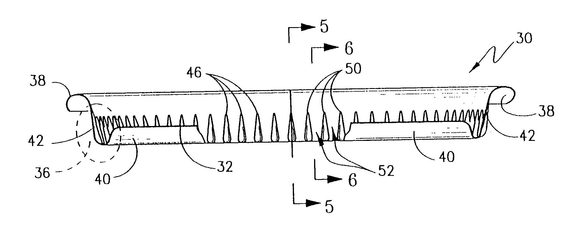
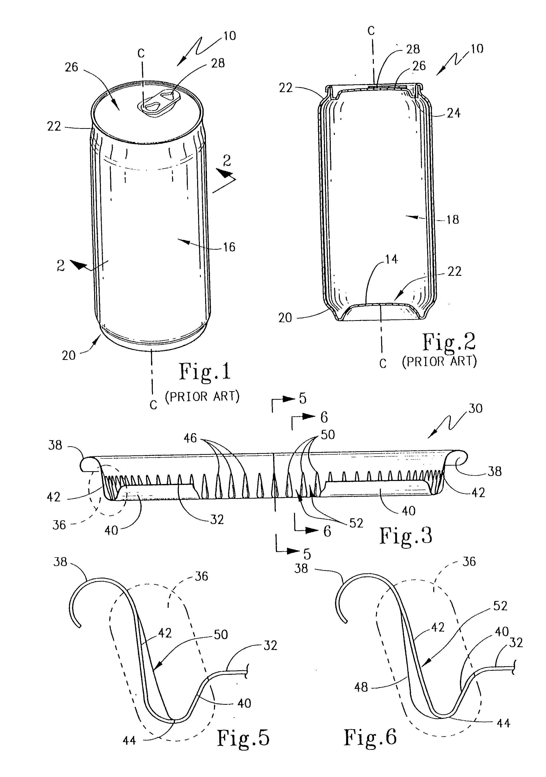
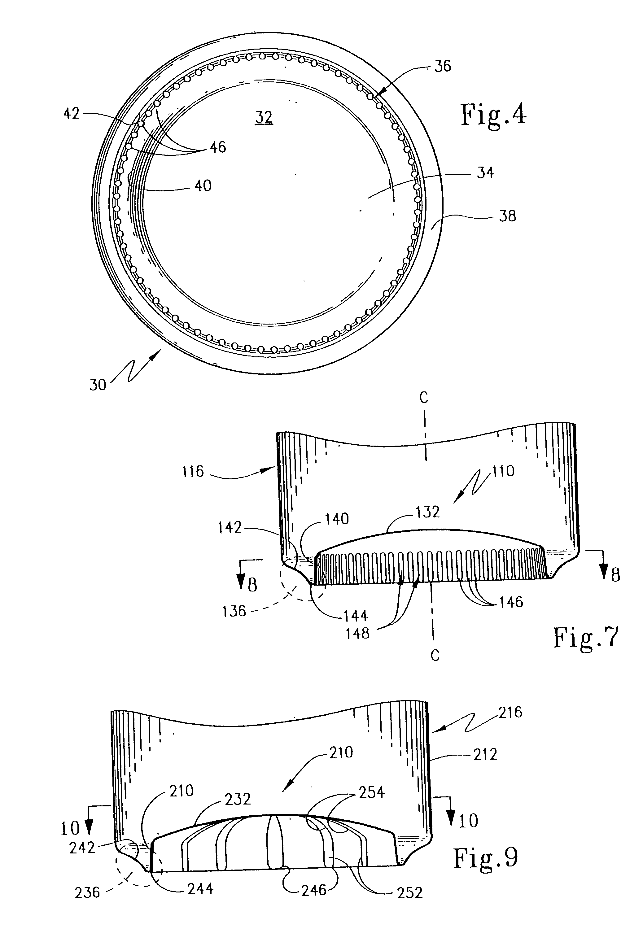
[0046] Turning to FIGS. 7 and 8, an end closure according to the present invention is shown. Here, can body 116 has an end closure in the form of a domed bottom 110 that includes a dome-shaped central body panel 132 that extends transversely of central axis “C”. Domed bottom 110 provides an end closure that is opposite the end where the lid, such as lid 26 or 30, is seamed onto the container. Central body panel 132 has an outer surrounding margin portion 136 that is generally U-shaped in configuration and includes an inner wall portion 140 that is oriented generally parallel to axis “C” and that is joined to an outer wall portion 142 by connecting wall 144. Walls 140 and 142 again provide a support section that is oriented longitudinally relative to the container body and a plurality of rib structures 146 are again provided. Here, wall portions 140, 142 and 144 along with central body panel 136 are formed integrally with side wall 112 of can body 116 as an integral, one-piece constr...
third embodiment
[0047] the present invention is shown in FIGS. 9 and 10. Here, can body 216 has a side wall 212 to which a domed end closure 210 is formed integrally as a one-piece construction therewith. To this end, domed end closure has a central body panel 232 that has an outer margin portion 236 that includes an inner wall portion 240 joined to an outer wall portion 242 by means of a connecting wall 244 to form a generally U-shaped profile. A plurality of rib structures 246 are again equidistantly and equiangularly spaced around dome end closure 210. To this end, rib structures 246 have first rib components 252 that are formed in inner wall portion 240 with second rib components 254 extending onto central body panel portion 232.
fourth embodiment
[0048] the present invention is shown in FIGS. 11 and 12. With reference to these Figures, then, it may be seen that a can body 316 has a side wall 312 which has a rectangular (in this instance square) in cross-section. Can body 316 has a domed end closure 310 including a central body 332. Outer margin portion 336 is formed by an inner wall portion 340 joined to an outer wall portion 342 by means of a connecting wall 344 in a manner similar to that described with respect to FIGS. 7-10. Here, inner wall portion 340 is a truncated pyramid and is provided with a plurality of rib structures 346 formed as tear-dropped depressions 348 formed in inner wall 340. Depressions 348 again form troughs 350 that are separated by ridges 352. A structure shown in FIGS. 11 and 12 is to illustrate that the can body according to the present invention as well as the resulting container can have a different geometric cross-section than the cylindrical cross-section shown in FIGS. 1-10. Here, again, centr...
PUM
| Property | Measurement | Unit |
|---|---|---|
| geometric shape | aaaaa | aaaaa |
| geometric shapes | aaaaa | aaaaa |
| diameter | aaaaa | aaaaa |
Abstract
Description
Claims
Application Information
 - R&D
- Intellectual Property
- Life Sciences
- Materials
- Tech Scout
- Unparalleled Data Quality
- Higher Quality Content
- 60% Fewer Hallucinations
Browse by: Latest US Patents, China's latest patents, Technical Efficacy Thesaurus, Application Domain, Technology Topic, Popular Technical Reports.
© 2025 PatSnap. All rights reserved.Legal|Privacy policy|Modern Slavery Act Transparency Statement|Sitemap|About US| Contact US: help@patsnap.com


