
Hand tool for inserting and removing rail fastenings

a technology for rail fastenings and hand tools, which is applied to railway tracks, track maintenance, construction, etc., can solve the problems of limited working strokes and hard work of hand tools of the present day

Inactive Publication Date: 2005-02-10
SOCIETE DES ANCIENS ESTABLISSEMENTS LUCIEN GEISMER
View PDF3 Cites 12 Cited by
  • Summary
  • Abstract
  • Description
  • Claims
  • Application Information

AI Technical Summary

Benefits of technology

[0026] in addition, the hydraulic power assistance gives the active part of the tool a larger stroke, allowing fastenings to be positioned in different positions with respect to the rail, all within the same movement, without the active part of the tool, or even the complete tool, having to be changed to reach these different positions.

Problems solved by technology

If he is working on a double or multiple track, the operator is thus moving outside of the gage of the track to be worked on and is entering the gage of the adjacent track, which is a dangerous situation from the point of view of personal safety, because there may be trains traveling on this adjacent track (even if the track to be worked on is of course not in use); existing hand tools are specialized for a single task, that is they are tools that can only insert or only remove fastenings.
Two different types of tool must therefore be available, and must be used alternately depending on whether one is inserting or removing a fastening; owing to the fact that their principle of operation is purely mechanical (with a lever), present-day hand tools continue to be hard work, and yet with a given driving movement still produce only a limited working stroke.

Method used


Image

  • Hand tool for inserting and removing rail fastenings
  • Hand tool for inserting and removing rail fastenings
  • Hand tool for inserting and removing rail fastenings

Examples


Embodiment Construction

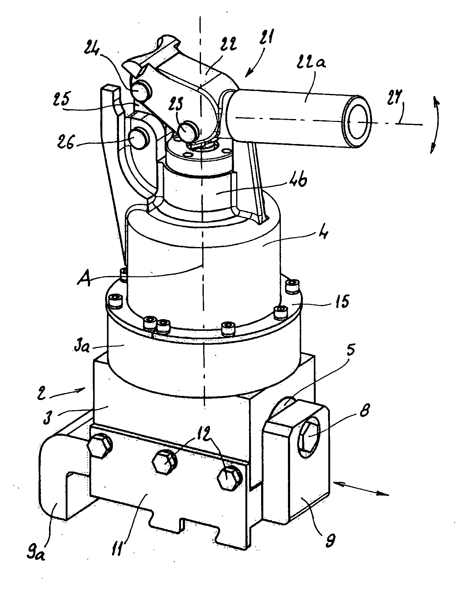
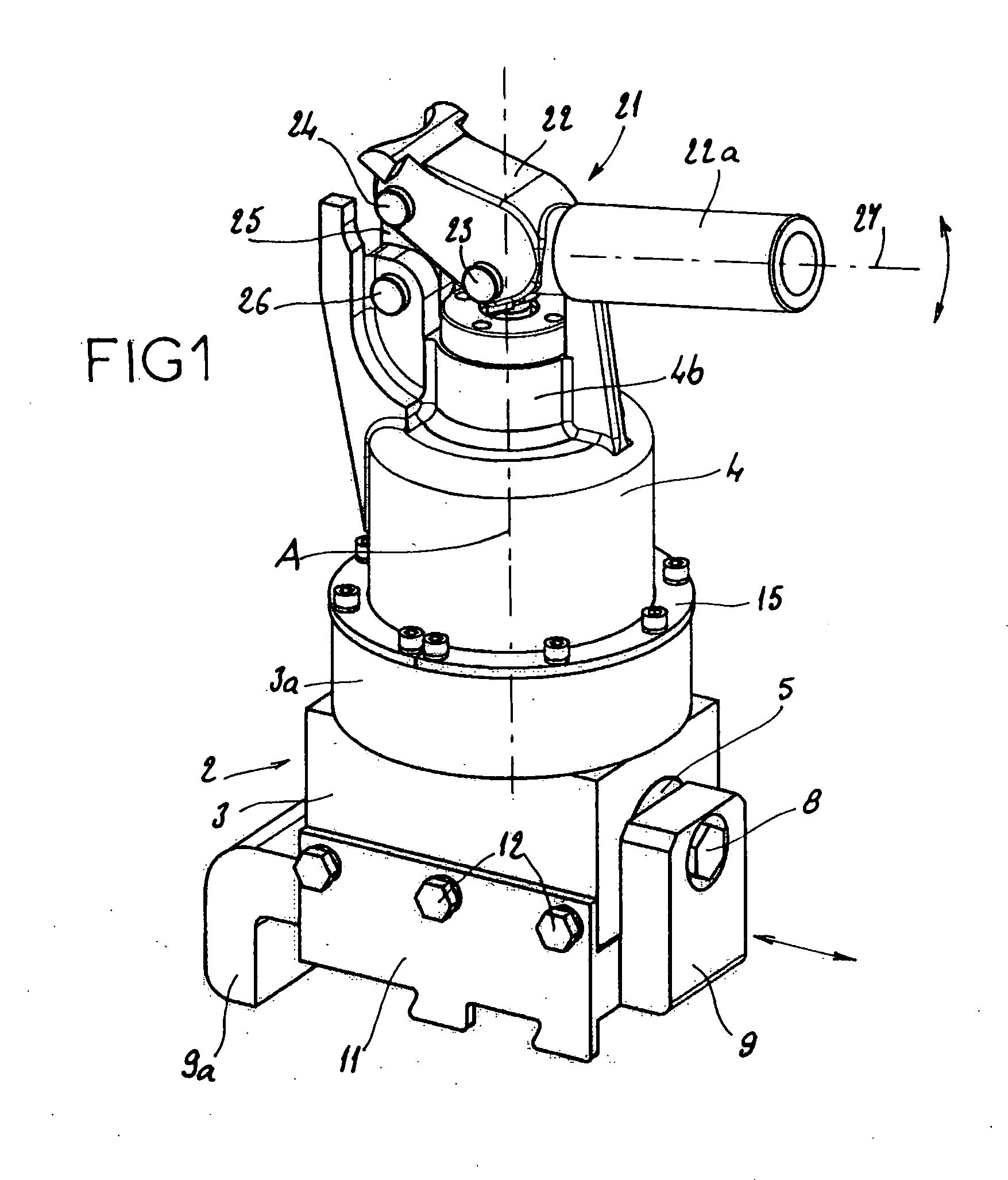
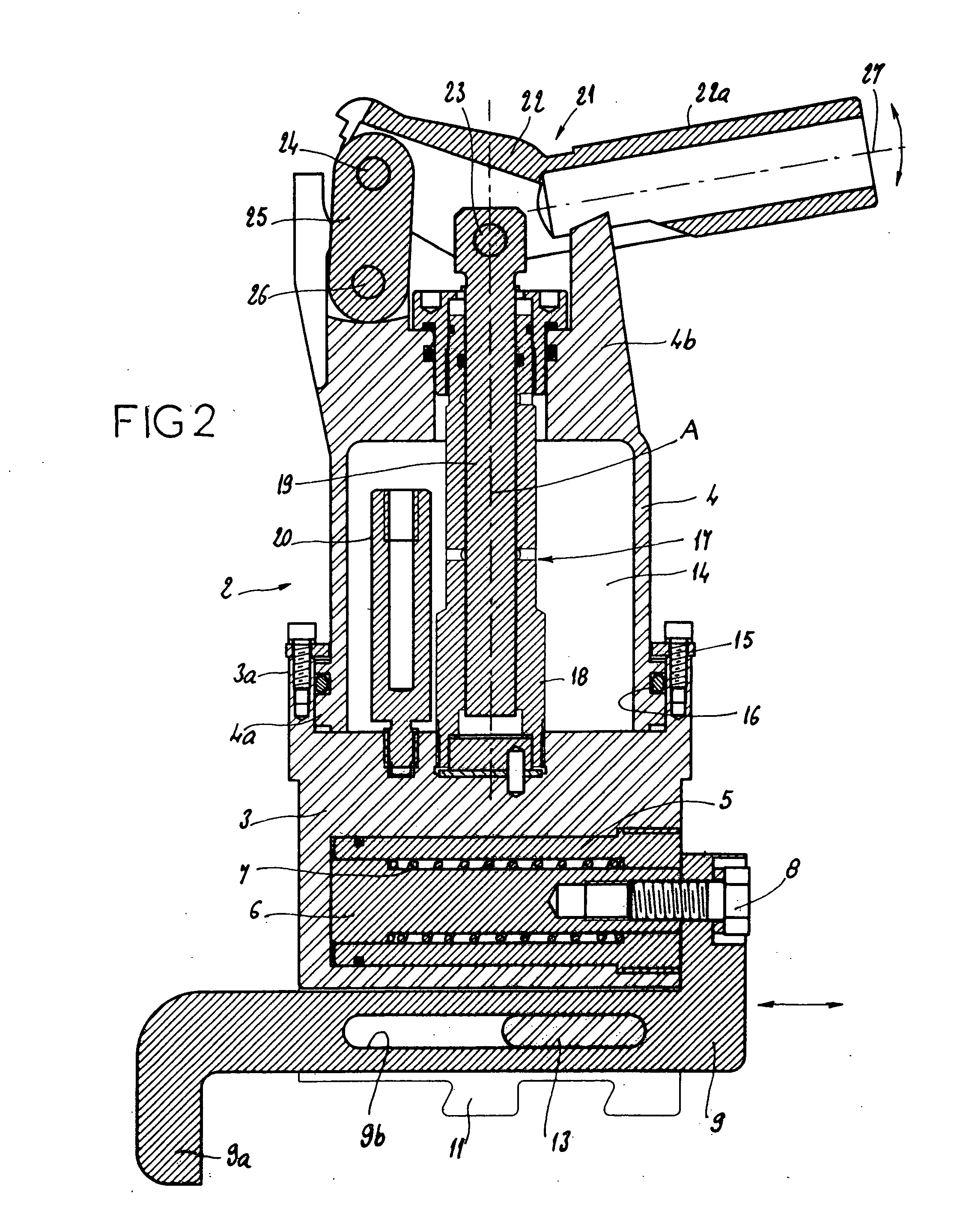
[0032] The hand tool for inserting and removing rail fastenings, as shown in the drawing, FIGS. 1 and 2 in particular, is denoted as a whole by the reference number 2. Hand tool 2 comprises a main body consisting of a base block 3 surmounted by a rotating part 4.

[0033] The base block 3 houses a fixed cylinder 5, of essentially horizontal axis, in which slides a piston 6, subjected to the action of a restoring spring 7 which pushes the piston 6 towards the closed end of the cylinder 5, the whole forming a hydraulic ram.

[0034] To the outward end of the piston 6 there is fixed, by means of a screw 8, an insertion cam 9 which is the active part of the tool and acts on the fastening that is to be inserted or removed, notably by an end 9a which is bent down at right angles.

[0035] The insertion cam 9 slides on the underside of the base block 3 between two toothed outer plates 11 fixed laterally to either side of the base block 3 by means of screws 12. The insertion cam 9 contains a long...


PUM

PropertyMeasurementUnit
poweraaaaaaaaaa
cylindrical volumeaaaaaaaaaa
elasticaaaaaaaaaa

Abstract

This hand tool is designed for installing and extracting the elastic fastenings of railroad rails. It comprises a base body, mounted movably to the underside of which is an active part which acts on the fastening that is to be inserted or removed. A rotating head or a rotating part that can be pivoted about an essentially vertical axis is provided on the top of the main body, this head carrying a hand-powered member such as a push bar which extends to the side of said head. A force-multiplying transmission, which may for example be hydraulic, connects the hand-powered member to the active part. In this way the hand-powered member can, independently of the use position of the active part, be placed in a suitable orientation, particularly inside a safe zone.

Description

[0001] The present invention relates to a hand tool for inserting and removing fastenings of railroad rails, this tool being more particularly designed for installing and extracting the elastic fastenings of rails, also known in the trade as clips. BACKGROUND OF THE INVENTION [0002] Such removable fastenings are inserted into a fixed support embedded in a tie in the railroad to hold the rail in place. These fastenings are applied to both the inner and outer flanges of the rail foot, i.e. the bottom part of the rail which is laid on the ties. DESCRIPTION OF THE PRIOR ART [0003] Three categories of equipment are currently known for inserting and removing such rail fastenings: [0004] a) some are highly efficient self-propelled machines which travel along the actual rails of the railroad, carrying the machine driver with it. The power for moving and working the machine is supplied by a heat engine and by a high-power hydraulic power unit, both on board the machine; [0005] b) some are li...

Claims


Application Information

Patent Timeline
Patent Type & Authority Applications(United States)
IPC IPC(8): E01B29/24
CPCE01B29/24Y10T29/53843Y10T29/5383Y10T29/49826
Inventor ROUSSET, BERNARD
Owner SOCIETE DES ANCIENS ESTABLISSEMENTS LUCIEN GEISMER
Learn More