
Method and device for determining the pressure in the combustion chamber of an internal combustion engine, in particular a spontaneous ignition engine, for controlling fuel injection in the engine

a technology of internal combustion engine and pressure measurement, which is applied in the direction of braking system, position/direction control, structural/machine measurement, etc., can solve the problems of poor reliability, unsatisfactory performance, and inability to adopt closed-loop control strategies

Active Publication Date: 2005-02-03
STMICROELECTRONICS SRL
View PDF15 Cites 41 Cited by
  • Summary
  • Abstract
  • Description
  • Claims
  • Application Information

AI Technical Summary

Benefits of technology

The present invention provides a method and device for measuring pressure in the combustion chamber of an internal combustion engine, particularly a spontaneous ignition engine, without the need for a sensor in the chamber. This method and device can provide accurate and reliable data, while also being cost-effective and easy to use. Additionally, the invention provides a method and device for controlling fuel injection in the engine, which can also improve performance and efficiency.

Problems solved by technology

In general, the cost limits imposed by the automobile market on cars make it practically impossible to adopt closed-loop control strategies, which can be achieved only for research purposes in specially set-up laboratories, and allow only the adoption of open-loop control strategies operating on the basis of maps memorized in the electronic control unit and experimentally defined on the work-bench during the engine design phase, with all the consequences that may ensue from the absence of feedback, such as poor reliability and unsatisfactory performances.
However, the closed-loop control described above is applicable only in the laboratory on experimental prototypes and cannot at the moment be adopted on cars intended for the market due not only to the high cost of the dynamic pressure sensor but above all due to the numerous problems deriving from the use of the pressure sensor such as its bulk in the combustion chamber, the need for its periodic maintenance and replacement due to wear, since it is subject to the high pressures and temperatures present in the combustion chamber, replacement which, inter alia, would require an estimate of its average life cycle, and last but not least the need to provide a specific electronic device that manages it (an amplifier, a sophisticated filter, a current-voltage-pressure converter).

Method used


Image

  • Method and device for determining the pressure in the combustion chamber of an internal combustion engine, in particular a spontaneous ignition engine, for controlling fuel injection in the engine
  • Method and device for determining the pressure in the combustion chamber of an internal combustion engine, in particular a spontaneous ignition engine, for controlling fuel injection in the engine
  • Method and device for determining the pressure in the combustion chamber of an internal combustion engine, in particular a spontaneous ignition engine, for controlling fuel injection in the engine

Examples


Embodiment Construction

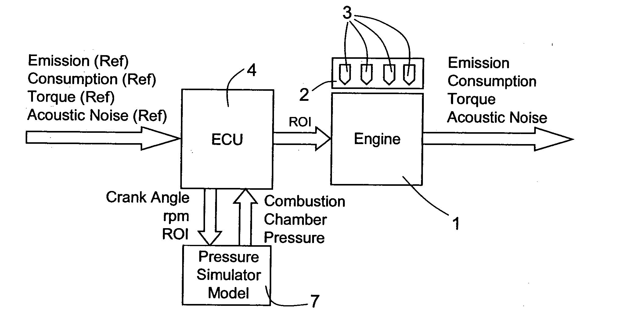
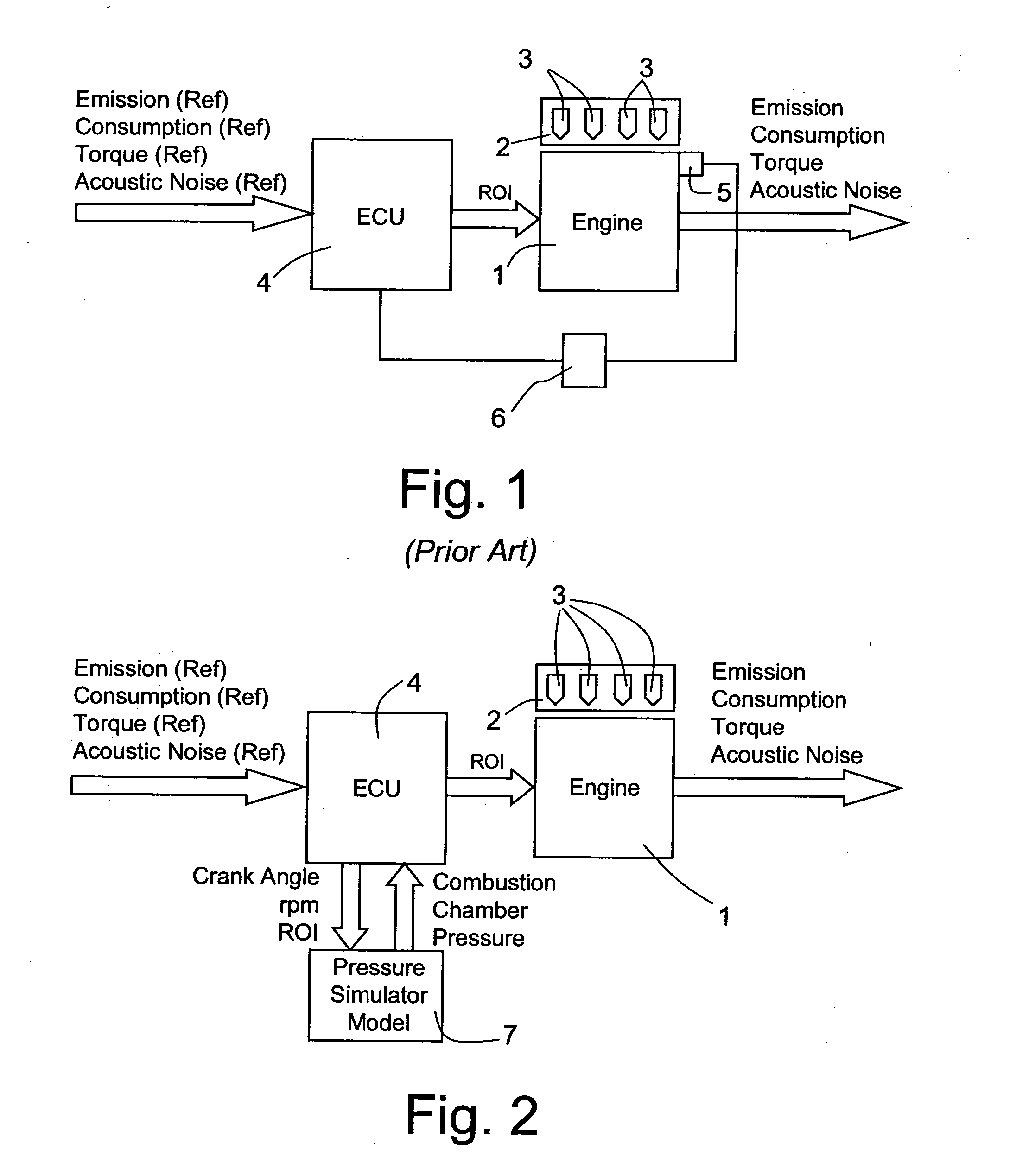
The idea underlying the present invention is providing a determining device actually constituting a virtual pressure sensor external to the combustion chamber, able to assess in real time the pressure in the combustion chamber, in the manner described below in detail, and to supply to the electronic control unit a pressure signal completely equivalent to the one supplied by a dynamic pressure sensor used in laboratory, and actually constituting a virtual feedback signal that can be directly used by the electronic control unit to closed-loop control the above-mentioned car quantities.

In this way it is actually possible to realize a closed-loop control system completely equivalent to that used in laboratory but without the need of a pressure sensor arranged in the combustion chamber, thus allowing its adoption on cars intended for the market.

FIG. 2 shows a schematic block diagram of a control system using a virtual sensor according to the present invention. As can be seen, the ins...


PUM


Abstract

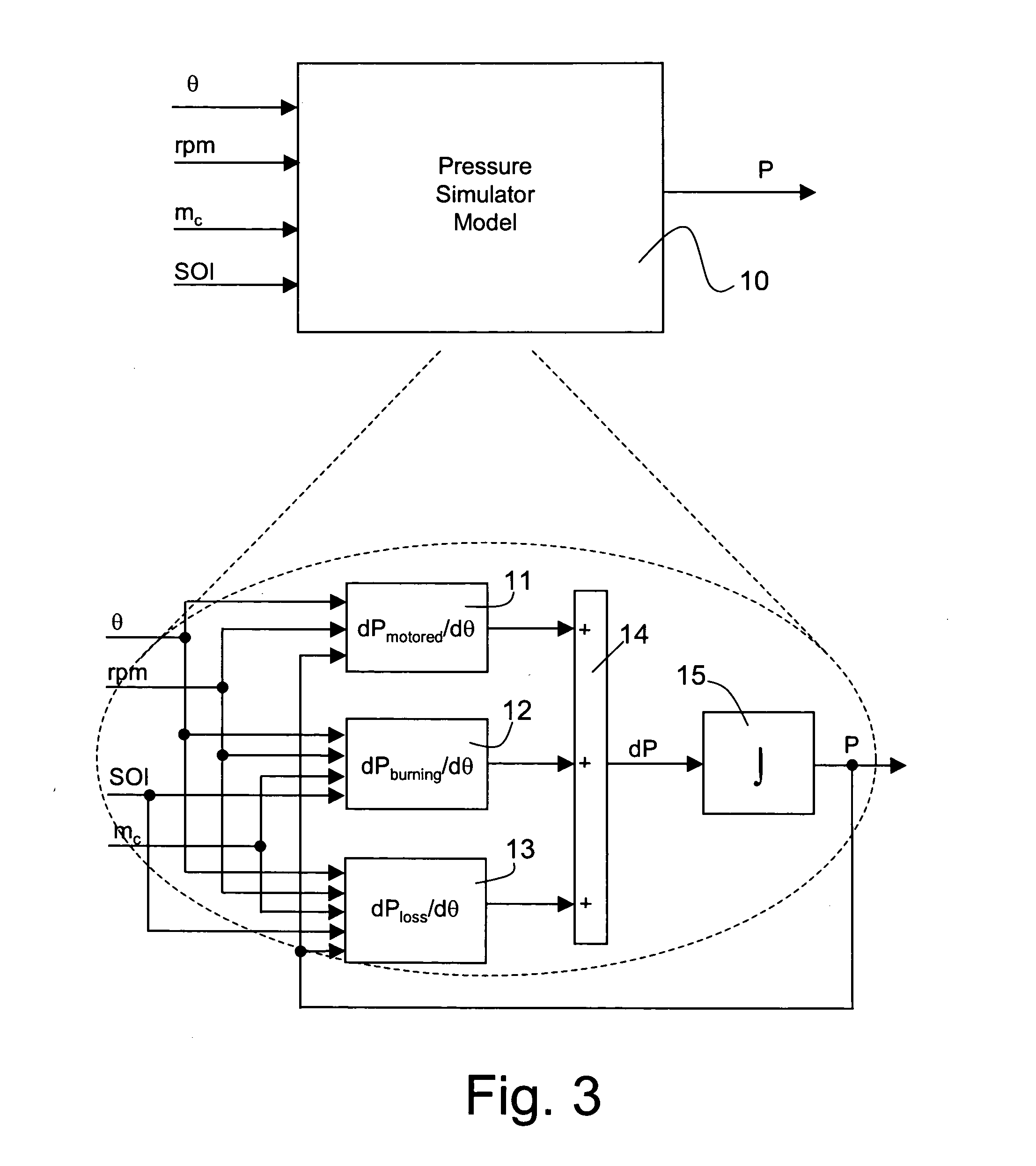
A method is described for controlling fuel injection in an spontaneous ignition engine equipped with an electronically controlled fuel injection system and with an electronic control unit receiving engine quantities comprising the pressure in the combustion changer of the engine and closed-loop controlling the fuel injection system on the basis of the pressure in the combustion chamber, in which the pressure in the combustion chamber is determined as a function of engine kinematic quantities such as the engine speed and the crank angle and of the fuel injection law, which is defined by the quantity of fuel injected and by the crank angle at the start of injection.

Description

BACKGROUND OF THE INVENTION 1. Field of the Invention The present invention concerns a method and a device for determining the pressure in the combustion chamber of an internal combustion engine, in particular a spontaneous ignition engine. The present invention also concerns a method and a device for controlling fuel injection in an internal combustion engine, in particular a spontaneous ignition engine, using said method for determining the pressure in the combustion chamber. 2. Description of the Related Art As is known, the cars currently on the market are equipped with a complex and sophisticated control system that is able to implement complex control strategies with the aim of optimizing, on the basis of information received from physical on-board sensors, certain important engine quantities such as consumption, exhaust emission levels, engine torque, and acoustic noise produced by the engine. In general, the cost limits imposed by the automobile market on cars make it ...

Claims


Application Information

Patent Timeline
Patent Type & Authority Applications(United States)
IPC IPC(8): F02B1/12F02D35/02F02D41/14F02D41/30
CPCF02B1/12F02D35/024F02D2041/1433F02D41/1497F02D41/3035F02D41/1401
Inventor PALMA, GIUSEPPESCOGNAMIGLIO, OLGALAVORGNA, MARIO
Owner STMICROELECTRONICS SRL
Learn More