
Suspension system

a suspension system and suspension technology, applied in the direction of resilient suspensions, interconnection systems, vehicle springs, etc., can solve the problems of complex active, ineffective countering the dynamic rolling force, and traditional suspension systems suffer from a lack of interactive “feel” for the road and the special requirements of adaptive flexibility, so as to optimize the performance of the suspension system. , the effect of improving the suspension performan

Inactive Publication Date: 2005-01-27
TORQUE TRACTION TECH INC
View PDF10 Cites 43 Cited by
  • Summary
  • Abstract
  • Description
  • Claims
  • Application Information

AI Technical Summary

Benefits of technology

[0007] The invention comprises a suspension control system that imparts a variable supplemental resistive force to control vehicle body roll and improve suspension performance through the use of magnetic rheological force devices. The force devices may be mounted separately in a modular-type configuration, or they may be installed as an integral part of a conventional suspension assembly system. Additionally, vehicles originally produced without the force devices may be retrofitted to include the devices. Each of the

Problems solved by technology

Although passive suspension systems are somewhat effective on straight relatively smooth roads, they are not as effective in countering the dynamic rolling forces experienced by rapidly turning vehicles.
Traditional suspension systems also suffer from a lack of interactive “feel” for the road and the adaptive flexibility particularly required by sports cars or off road vehicles.
The prior art also includes complex active suspension systems designed to actively detect and counter virtually every road surface-related variation.
While these systems deliver near-optimal suspension results, they are also extremely expensive to produce, install, and maintain, and they are vulnerable to hardware and software failures as a result of their complex and extensive hardware and software designs.

Method used


Image

  • Suspension system
  • Suspension system
  • Suspension system

Examples


Embodiment Construction

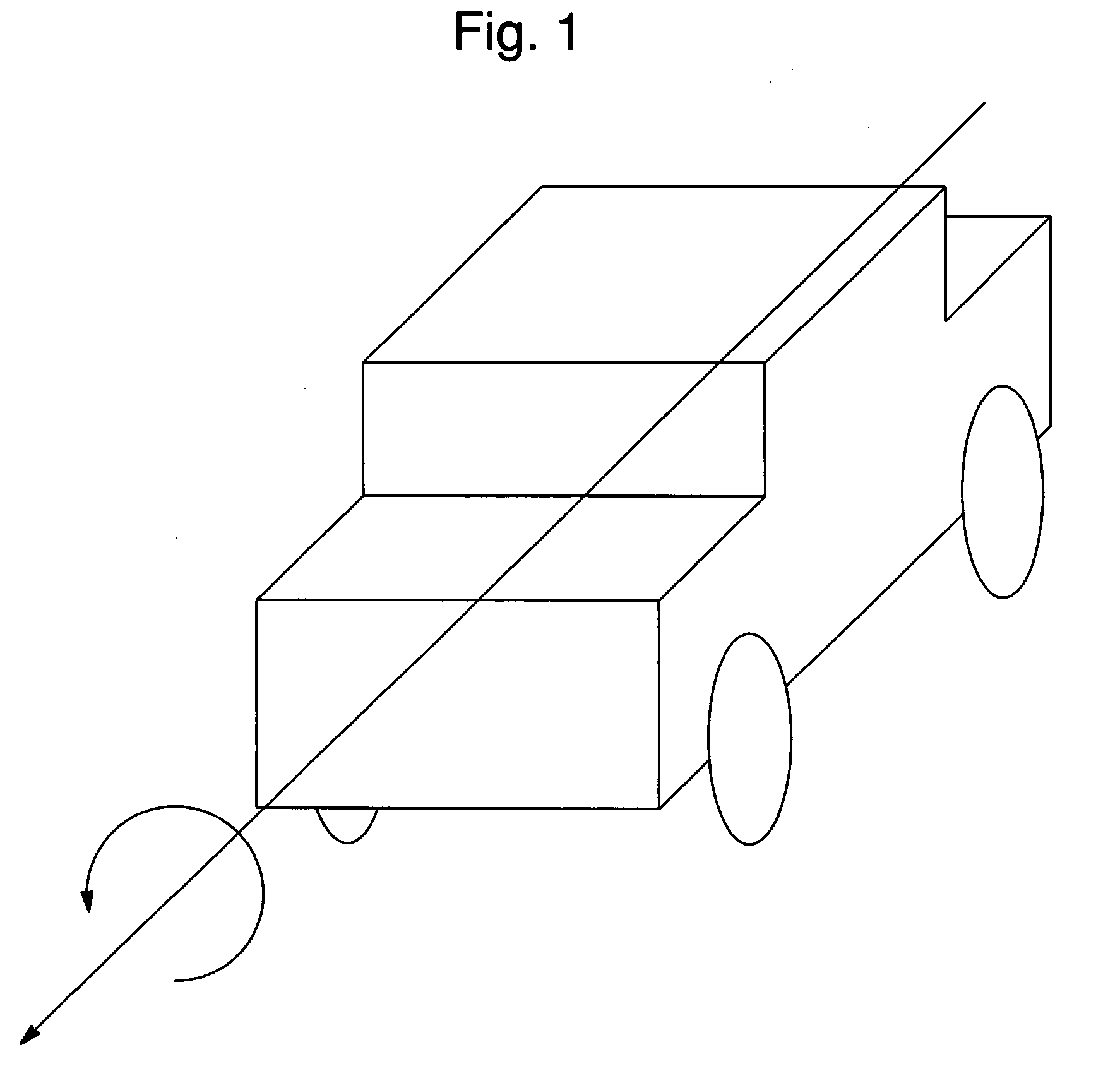
[0014] The present invention is an active drop link roll control system that imparts a variable supplemental resistive force to control the roll characteristics of a motor vehicle. FIG. 1 illustrates the roll axis of a typical automobile. To control movement about the roll axis, the present invention employs a suspension system enhanced by magnetic rheologic force devices and controlled by a logic unit.

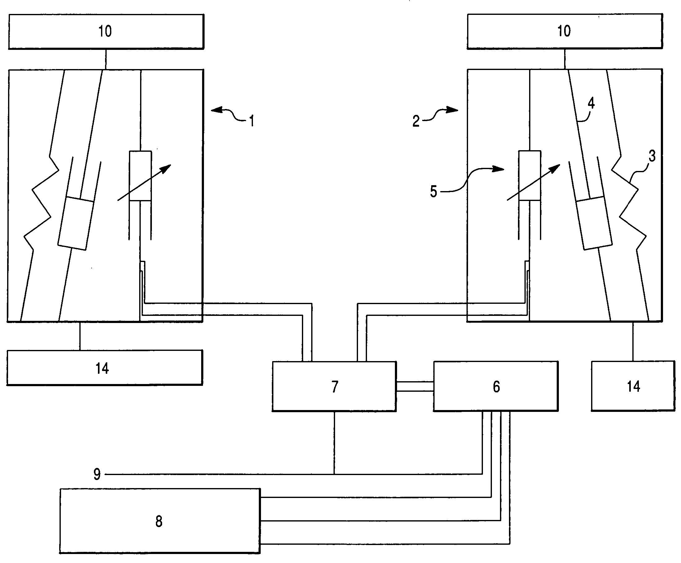
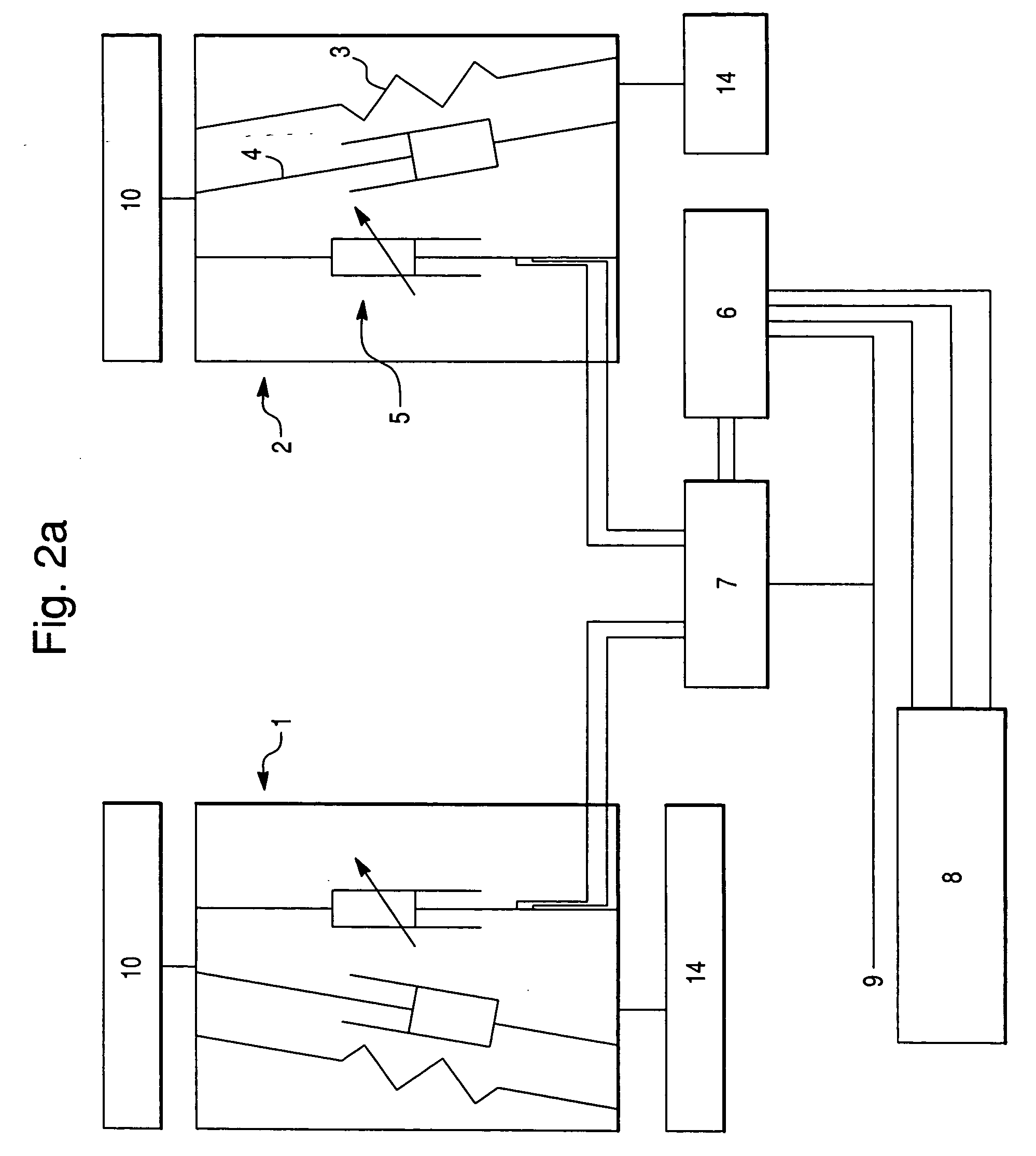
[0015]FIGS. 2a-2d and 3 are schematics illustrating the active drop link roll control system of the present invention. As best shown in FIG. 2a, the system is comprised of at least two suspension assemblies (1, 2) corresponding to individual wheels, or more generally, to the sides of a vehicle. The suspension assembly comprises shock absorbers (3) and coil springs (4) to provide a vehicle with conventional passive suspension support. The suspension further includes an energy absorbing magnetic rheologic force device (5) positioned between the wheel support members (14) and the vehicl...


PUM


Abstract

A suspension control system designed to impart a variable supplemental resistive force to control vehicle body roll and to improve suspension performance through the use of magnetic rheologic force devices. Each of the force devices impart rheologically adjustable amounts of force and resistance to the vehicle suspension system based on a variable magnetic / electrical field created within the force devices. The control system further includes a plurality of sensors that monitor vehicle components and performance parameters, and send signals to a logic unit. The logic unit processes input from the sensors and sends electrical commands to the force devices, which take the appropriate action to optimize suspension system performance. The use of the magnetic rheological force devices supplants traditional stabilizer bars and the associated linkages, fasteners, brackets and insulators.

Description

BACKGROUND OF THE INVENTION [0001] 1. Field of the Invention [0002] The invention generally relates to suspension systems. Specifically, the invention relates to suspension systems for motor vehicles, such as automobiles, busses and trucks. [0003] 2. Description of the Related Art [0004] A typical motor vehicle suspension system comprises a passive system of shocks, springs, and stabilizer components arranged to dampen road surface vibrations and road surface anomalies commonly encountered by motor vehicles. Although passive suspension systems are somewhat effective on straight relatively smooth roads, they are not as effective in countering the dynamic rolling forces experienced by rapidly turning vehicles. Traditional suspension systems also suffer from a lack of interactive “feel” for the road and the adaptive flexibility particularly required by sports cars or off road vehicles. [0005] The prior art also includes complex active suspension systems designed to actively detect and ...

Claims


Application Information

Patent Timeline
IPC IPC(8): B60G17/00B60G17/005B60G17/015B60G17/018B60G21/10
CPCB60G17/015B60G17/018B60G2202/22B60G2400/41B60G2400/204B60G2400/252B60G2400/104
Inventor KROPPE, WILLIAM J.
Owner TORQUE TRACTION TECH INC
Learn More