Mobile object with force generators

a technology of force generators and mobile objects, applied in the field of flying objects, can solve the problems of large wings of aircraft, high cost of lifting and landing, and large blades of aircraft's rotors, and achieve the effect of reducing the cost of lifting and landing

Inactive Publication Date: 2005-01-27
MINH VU XUAN
View PDF2 Cites 8 Cited by
  • Summary
  • Abstract
  • Description
  • Claims
  • Application Information

AI Technical Summary

Benefits of technology

Accordingly, the main objects and advantages of my invention are to provide vehicles with mechanisms which allow the vehicles to generate their own total internal force that is their self-action force for starting, accelerating, lifting, landing, and moving in any direction in the air, cosmos, and water (if it is sealed), and on any ground surface and water surface (if the lower part of its body is sealed). The vehicles will make the mankind's transport system much more flexible, simple, cheap, safe, and faster in both the earth's environment and universe.
The above and another objects, advantages and features of my invention will become apparent following examination of drawings and ensuing description herein:

Problems solved by technology

Using the external thrusts confines motion possibility of the vehicles, since the vehicles need complex structures and specific conditions for their motion.
For example, aircraft needs large wings and expensive airports for lifting and landing; helicopter needs very large blades of its rotor in comparison with its body.
Both of them cannot fly at very high altitude because of decreasing of the air density along the altitude of the atmosphere.
Spaceship needs an expensive starting complex and cannot accelerate any more after running out of fuel for jet propulsion.
Consequently, the mankind's transport systems are very complicated, expensive, and constrained, and have low safety.
So far there has been virtually no exploration of any other body, which can generate a sufficiently large total internal force for practical application in vehicle technology.

Method used


Image

  • Mobile object with force generators
  • Mobile object with force generators
  • Mobile object with force generators

Examples


Embodiment Construction

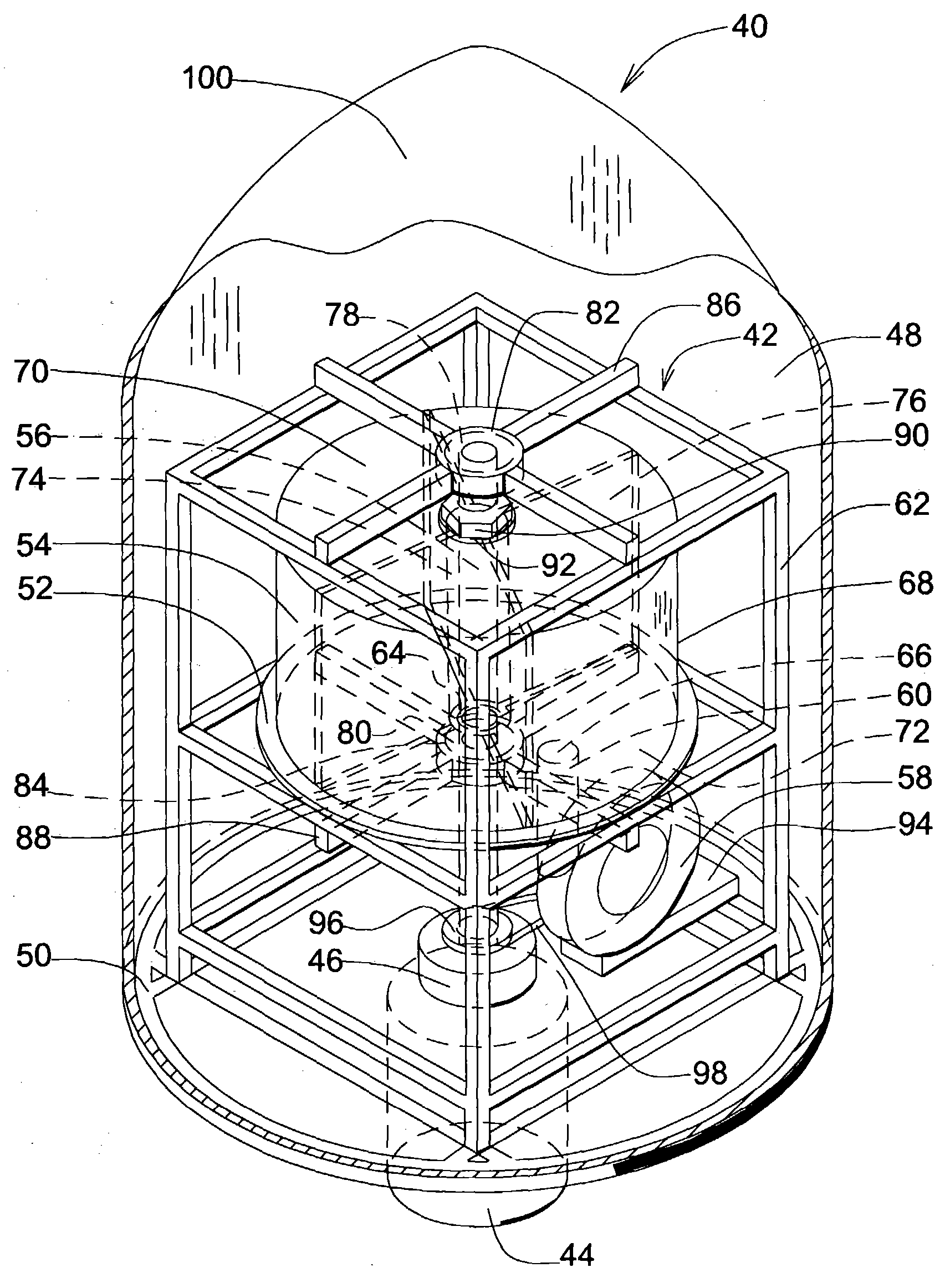
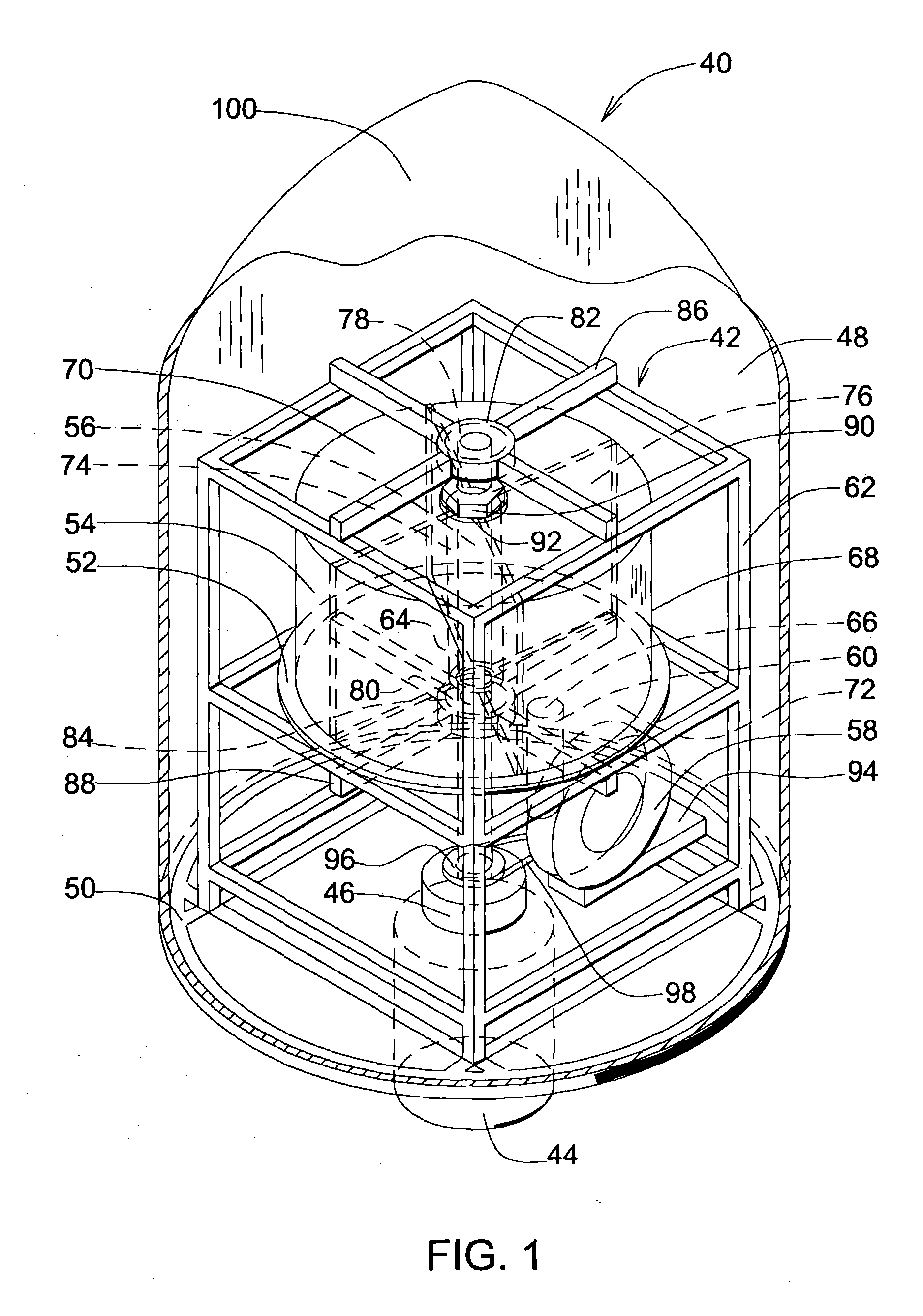
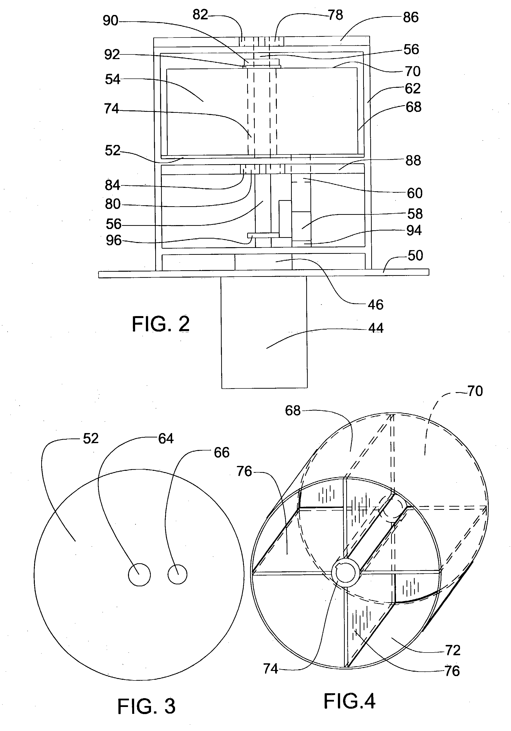
Referring now to the drawings, a mobile object constructed in accordance with one embodiment of the present invention is indicated generally at 40 in FIG. 1. Mobile object 40 includes a force generator indicated generally at 42, an engine 44, a gearbox 46, a generator chamber 48, and a structural frame 50. Force generator 42 comprises (see also FIG. 2) a disk-stator 52, a rotor 54, a shaft 56 of the rotor, a fan 58, a fan duct 60, and a generator frame 62. Disk-stator 52 (see also FIG. 3) is a disk having a central circular hole 64 as a free space for assembly of the disk-stator and the shaft, and a hole 66 being the outlet of fan duct 60. Rotor 54 comprises (see also FIG. 4) a circumferential tube 68 having its upper end closed by a top disk 70, an open bottom 72, a central tube 74 for the shaft assembly, and dividing walls 76. Dividing walls 76 extend from central tube 74 to circumferential tube 68 and from top disk 70 to open bottom 72 so that dividing walls 76 together with cen...


PUM


Abstract

A mobile object being a vehicle of any type includes a plurality of force generators, enclosed in a hermetically sealed generator chamber filled with a pressurized gas, and a plurality of engines. Each force generator being a lift device comprises a rotor, which includes a shaft, a rotary shell having an open bottom, and a means supporting the gas in relative equilibrium inside said rotary shell, and a stationary means closing said open bottom of said rotary shell. The specific coordination of the members of said force generator supports the gas on the lower surfaces of the force generator in relative equilibrium and hence produces the maximum difference between the pressures of the gas acting on the lower and upper surfaces of said force generator, i.e. the maximum lift. The force generators, enclosed in said generator chamber, produce the self-action force of said mobile object in accordance with the self-action principle of a solid-fluid body that has been established recently. By controlling the direction of the shafts and angular velocities of the force generators the mobile object can accelerate momentarily in any direction in space. The enclosure of the force generators in the generator chamber makes the self-action force of the mobile object independent of outer environment surrounding it. Any source of energy can be used for self-propulsion of the mobile object due to the direct conversion of the rotational energy into the self-action force without the use of material jets, reactive or external forces.

Description

FIELD OF THE INVENTION The invention relates to vehicle technology and specifically to flying objects. DISCUSSION OF PRIOR ART All the recent man-made vehicles start and accelerate, speed up or slow down, with the help of either external force, or reaction force, or jet, or their combination. The vehicles are passive in relation to those forces, because the forces are external. Using the external thrusts confines motion possibility of the vehicles, since the vehicles need complex structures and specific conditions for their motion. For example, aircraft needs large wings and expensive airports for lifting and landing; helicopter needs very large blades of its rotor in comparison with its body. Both of them cannot fly at very high altitude because of decreasing of the air density along the altitude of the atmosphere. Spaceship needs an expensive starting complex and cannot accelerate any more after running out of fuel for jet propulsion. Therefore, the maximum speed of the man-mad...

Claims


Application Information

Patent Timeline
Patent Type & Authority Applications(United States)
IPC IPC(8): B64C39/00F03H99/00
CPCB64C39/001F05B2200/11F05B2200/00F03H99/00B64C29/0025
Inventor MINH, VU XUAN
Owner MINH VU XUAN
Why Eureka
Try Eureka