
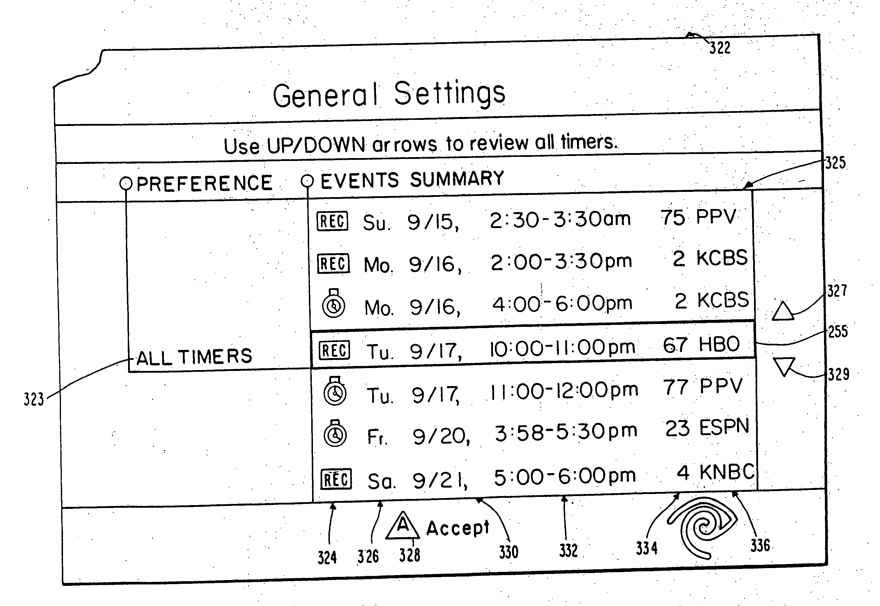
Interactive television program guide display

a technology of interactive television and program guide, which is applied in the field of television systems, can solve the problems of inability to deliver a high number of high quality television signals on a single coaxial cable, and many existing television systems cannot provide the advanced television services desired by their subscribers, and achieve the effect of high number and high quality television signals

Inactive Publication Date: 2005-01-20
TIME WARNER CABLE ENTERPRISES LLC
View PDF99 Cites 320 Cited by
  • Summary
  • Abstract
  • Description
  • Claims
  • Application Information

AI Technical Summary

Benefits of technology

[0009] It is therefore an object of this invention to provide a full service television system capable of delivering a high number of high quality television signals.
[0010] It is also an object of this invention to provide a full service television system capable of using advanced communication techniques to deliver a high number of high quality television signals.

Problems solved by technology

Traditional methods of broadcasting television programs and services in such cable television systems suffer from an inability to deliver a high number of high quality television signals on a single coaxial cable.
Many existing television systems also cannot provide the advanced television services desired by their subscribers, such as, for example, a comprehensive channel navigator, an interactive program guide, Impulse Pay-Per-view activation, Near-Video-On-Demand programming, Video-On-Demand programming, and advanced configuration controls.
Furthermore, most modern television systems have no provisions whatsoever for supplying services such as World Wide Web browsing, Internet E-Mail, and online services.

Method used


Image

  • Interactive television program guide display
  • Interactive television program guide display
  • Interactive television program guide display

Examples


Embodiment Construction

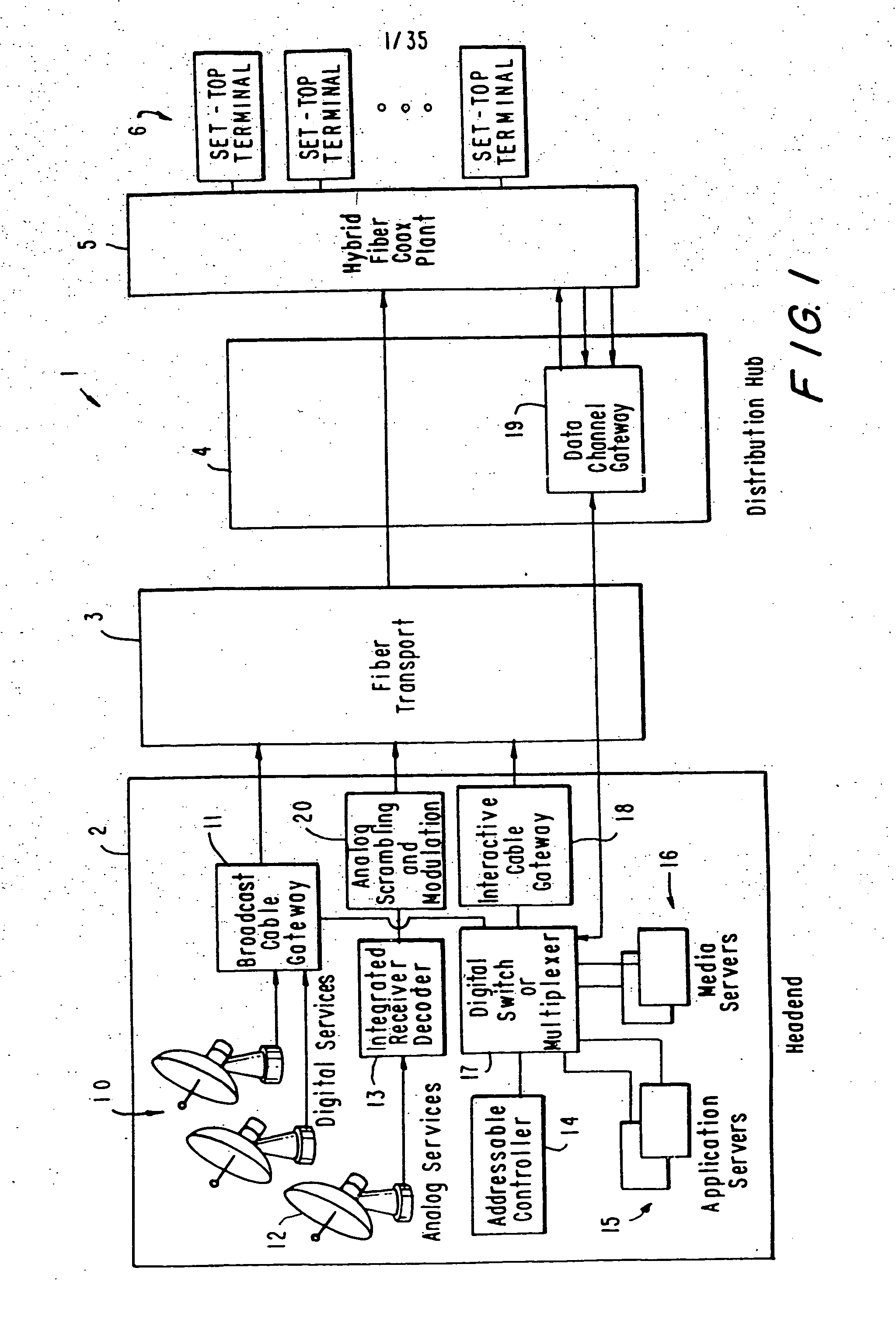
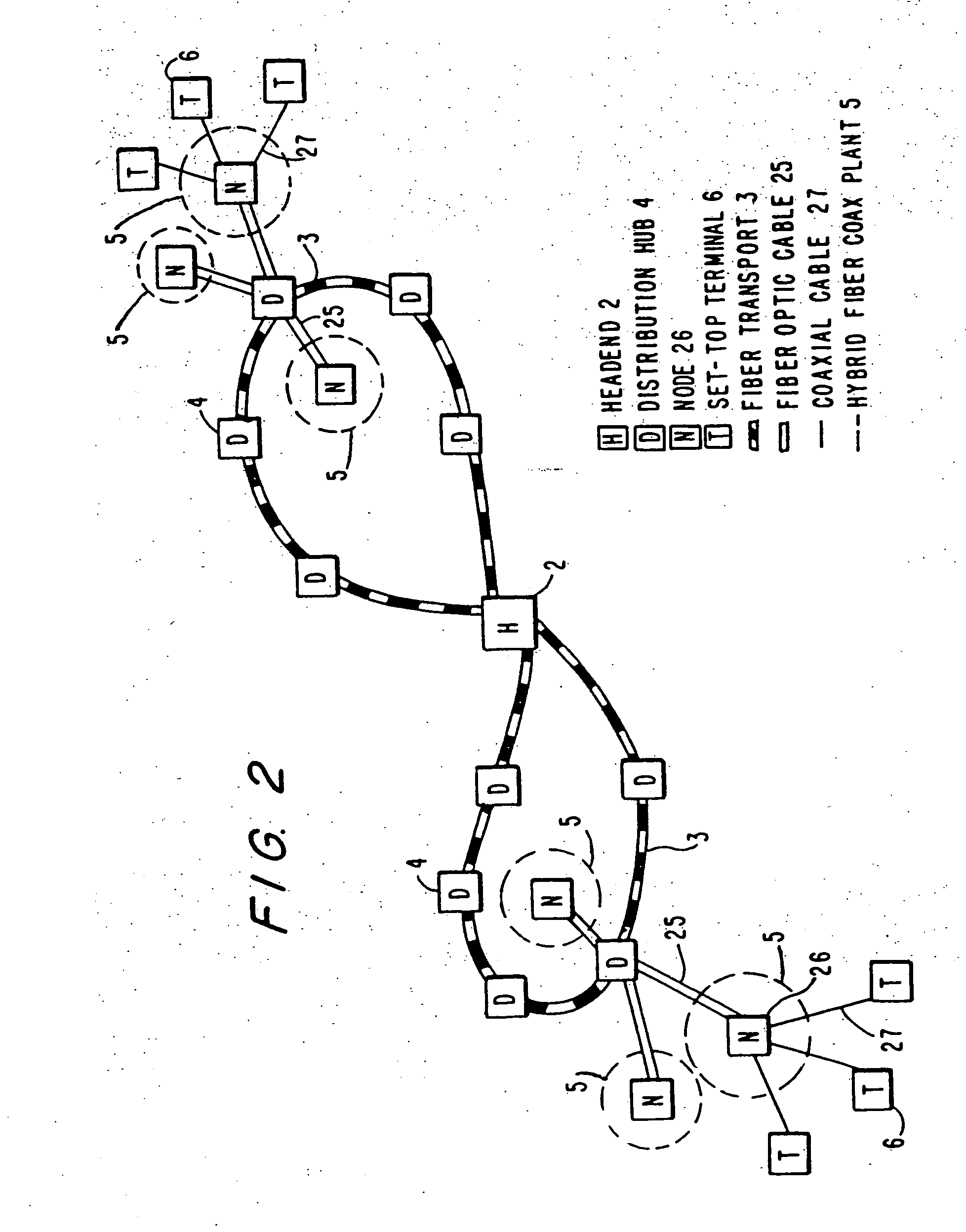
[0066] A cable television system 1 of a preferred embodiment of the present invention is shown in FIG. 1. Cable system 1 includes five primary components: a headend 2; at least one fiber transport 3; at least one distribution hub 4; at least one hybrid fiber coax plant 5; and a plurality of set-top terminals 6, typically located in the homes of subscribers. Headend 2 is the primary source of programs, services, and control of cable system 1. Programs, services, and control signals are delivered to subscribers' set-top terminals 6 from headend 2 by transmitting signals through fiber transport 3, distribution hub 4, and hybrid fiber coax plant 5. These transmissions can be in the form of broadcasts to all set-top terminals, narrowcasts to a group of set-top terminals, multicasts to a list of particular set-top terminals, or unicasts to a single set-top terminal. The present invention can be implemented as a one-way cable television system in which signals are only transmitted from hea...


PUM


Abstract

A full service cable television system and method are provided. The system comprises a cable headend, at least one fiber transport, at least one distribution hub, at least one hybrid fiber coax plant, and a plurality of set-top terminals. The system delivers television programs, advanced cable services, and online services. Programs and services are transmitted to the set-top terminals in both digital and analog formats to maintain downward compatibility with existing systems. The set-top terminal includes a central processing unit, a unified memory architecture, a memory management unit, communications circuitry, I / O control circuitry, and audio and video output circuitry. Through these components, the set-top terminal provides advanced cable services such as a comprehensive channel navigator, an interactive program guide, impulse Pay-Per-View, Near-Video-On-Demand and Video-On-Demand programming, and advanced configuration controls. The set-top terminal also provides online services such as World Wide Web browsing, Internet e-mail, and home shopping.

Description

CROSS REFERENCE TO RELATED APPLICATIONS [0001] This is a continuation of copending, commonly assigned U.S. patent application Ser. No. 09 / 185,179, filed Feb. 3, 1998, now U.S. Pat. No.______, which is a continuation of U.S. patent application Ser. No. 08 / 802,833, filed Feb. 19, 1997, now U.S. Pat. No. 5,850,218.BACKGROUND OF THE INVENTION [0002] This invention relates generally to television systems. More particularly, this invention relates to full service television systems that use advanced storage, communications, and processing techniques to provide a variety of television services including audio and audiovisual programming, advanced navigation controls, interactive program guides, Impulse Pay-Per-View activation, Near-Video-On-Demand programming, Video-On-Demand programming, advanced configuration controls, and online services. [0003] With recent advances in storage, communication, and processing technologies, many present-day television systems are becoming antiquated. This ...

Claims


Application Information

Patent Timeline
IPC IPC(8): H04N5/44H04N5/445H04N5/45H04N5/46H04N7/16H04N7/173H04N21/422H04N21/431H04N21/4402H04N21/462H04N21/47H04N21/475H04N21/4782H04N21/482H04N21/485H04N21/61H04N21/84
CPCH04N5/4401H04N21/84H04N5/44543H04N5/45H04N5/46H04N7/165H04N7/17318H04N21/42204H04N21/4316H04N21/4402H04N21/4622H04N21/47H04N21/4753H04N21/4782H04N21/4821H04N21/485H04N21/6118H04N5/44513H04N21/426
Inventor LAJOIE, MICHAEL L.BUEHL, JOSEPH G.KRAKIRIAN, HAIG H.JOHNSON, STEPHEN M.BROWN, RALPH W.
Owner TIME WARNER CABLE ENTERPRISES LLC
Learn More