
Apparatus and method for cleaning, painting and/or treating traffic barriers

a technology for traffic barriers and apparatus, applied in the field of apparatus for cleaning, painting and/or treating traffic barriers, can solve the problems of high labor intensity, inefficiency, and inability to clean the full length of many cement traffic barriers, and achieve the effect of constant quality of spraying material

Inactive Publication Date: 2005-01-20
KILLMER ROBERT M SR
View PDF5 Cites 21 Cited by
  • Summary
  • Abstract
  • Description
  • Claims
  • Application Information

AI Technical Summary

Benefits of technology

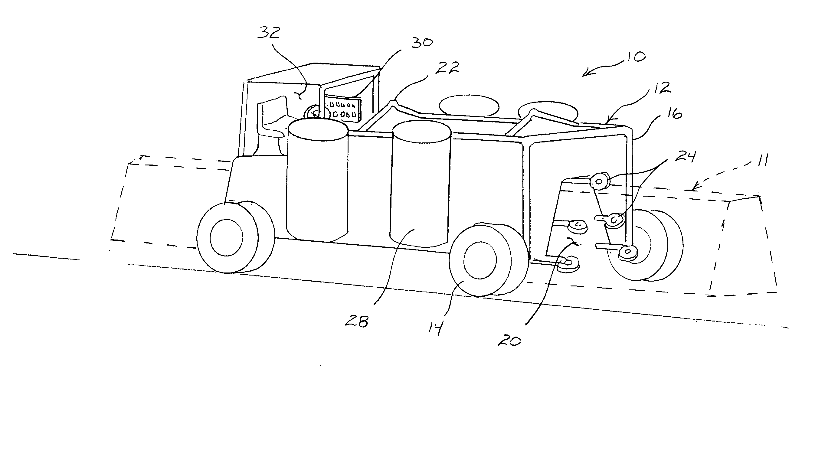
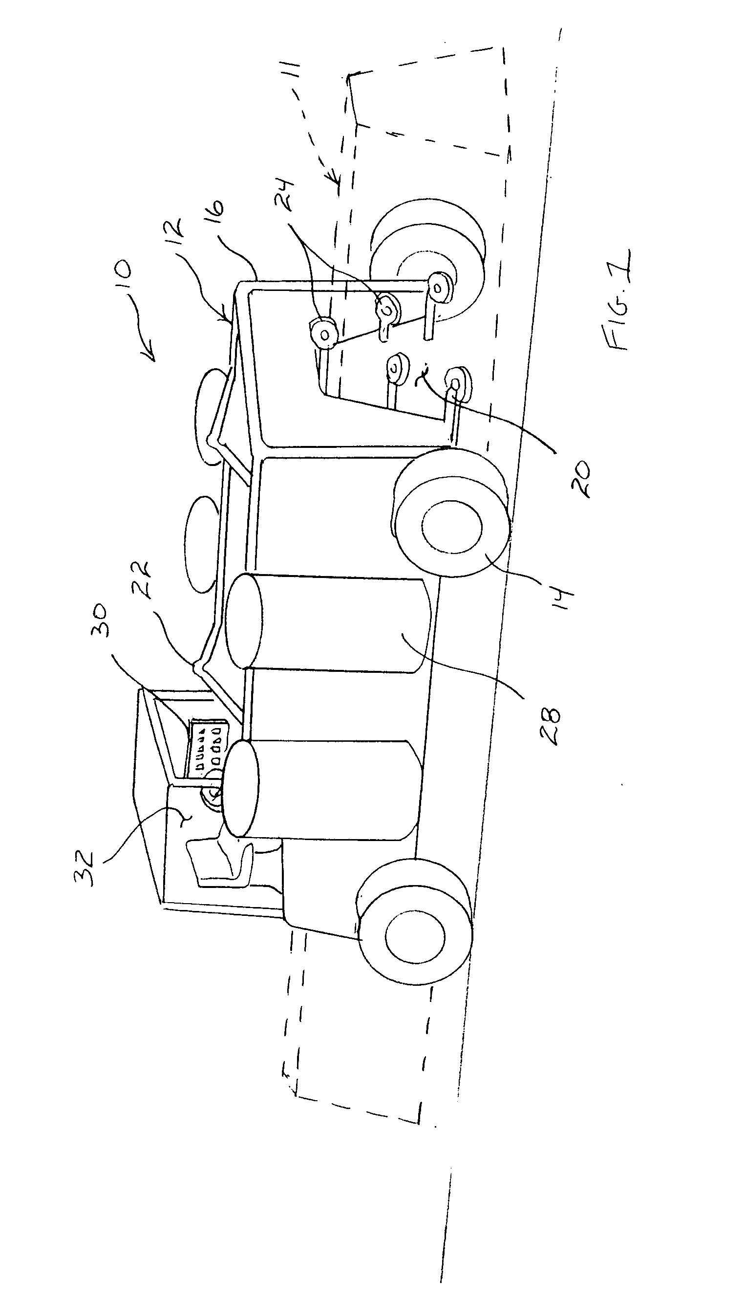
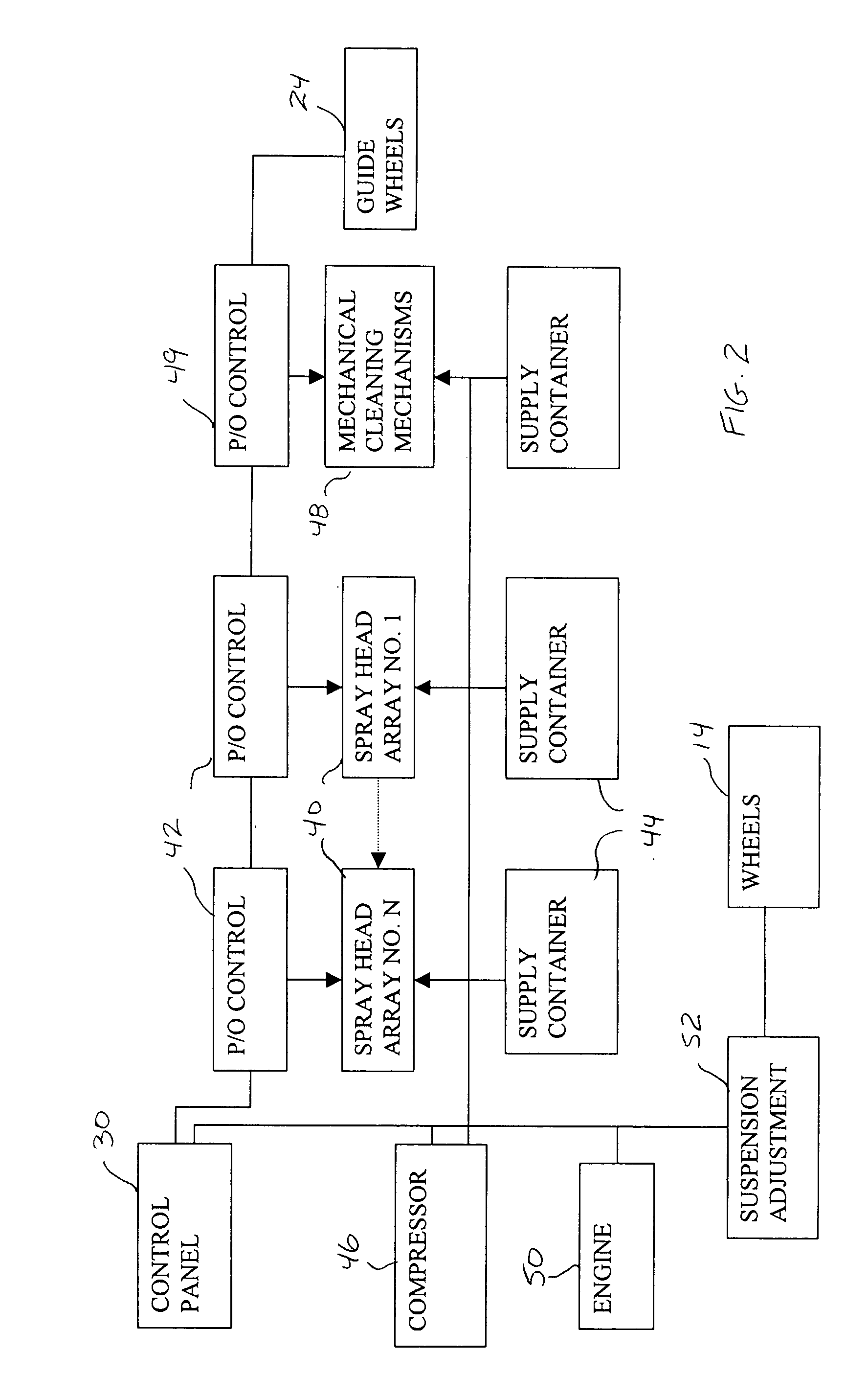
[0012] The present invention is an assembly and method for spraying material on a traffic barrier. The assembly includes at least one vehicle that travels along the length of the traffic barrier while contacting the traffic barrier and being guided by the traffic barrier. With each vehicle is one or more spray head arrays that spray the surfaces of the traffic barrier as the vehicle rolls along the traffic barrier. The spray heads can spray either cleaning material, such as air, water, cleaning solution, solvents and abrasives, or coating materials, such as paint or waterproofing solutions. Both cleaning and coating can be preformed by spray head arrays in the same vehicle or in different vehicles. The spray heads can be automatically adjusted to match variations encountered in the traffic barrier as the spray head arrays are moved along the traffic barrier. In this manner, the quality of the application of sprayed material remains constant despite changes in the shape, position, orientation and / or condition of the traffic barrier being sprayed.

Problems solved by technology

Using cleaning machines on articulating arms that clean only small sections at a time are not well suited for cleaning the full length of many cement traffic barriers.
Furthermore, relying upon manual labor to hold painting equipment and carry it along the length of the roadway is also highly labor intensive and inefficient.

Method used


Image

  • Apparatus and method for cleaning, painting and/or treating traffic barriers
  • Apparatus and method for cleaning, painting and/or treating traffic barriers
  • Apparatus and method for cleaning, painting and/or treating traffic barriers

Examples


Embodiment Construction

[0020] Although the present invention can be used to clean and / or paint many types of roadside structures, such as metal traffic barriers, stone traffic barriers and the like, the present invention is particularly well suited for cleaning and / or painting cement traffic barriers. As such, the present invention will be described and illustrated in an application where it is being used to clean and paint a cement traffic barrier in order to set forth the best mode contemplated for the invention.

[0021] Referring to FIG. 1, there is shown an exemplary embodiment of the present invention barrier maintenance assembly 10. In the shown embodiment the present invention barrier maintenance assembly 10 is configured as a self-propelled vehicle 12. The vehicle 12 is configured so that it can straddle a cement traffic barrier 11 and move along the length of the cement traffic barrier 11 under its own power. As will later be explained in more detail, the barrier maintenance assembly 10 is placed ...


PUM

PropertyMeasurementUnit
Lengthaaaaaaaaaa
Shapeaaaaaaaaaa
Dimensionaaaaaaaaaa

Abstract

An assembly and method for spraying material on a traffic barrier. At least one vehicle is provided that travels along the length of the traffic barrier while contacting the traffic barrier and being guided by the traffic barrier. With each vehicle is one or more spray head arrays that spray the surfaces of the traffic barrier as the vehicle rolls along the traffic barrier. The spray heads can spray either cleaning material or coating materials. Both cleaning and coating can be preformed by spray head arrays in the same vehicle or in different vehicles. The spray heads can be automatically adjusted to match variations encountered in the traffic barrier as the spray head arrays are moved along the traffic barrier. In this manner, the quality of the application of sprayed material remains constant despite changes in the shape and / or condition of the traffic barrier being sprayed.

Description

BACKGROUND OF THE INVENTION [0001] 1. Field of the Invention [0002] In general, the present invention relates to machines that automatically clean, paint or treat concrete surfaces. More particularly, the present invention relates to mobile machines that clean, paint or treat concrete surfaces as the machine moves along such surfaces. [0003] 2. Background of the Invention [0004] When roadways are created, it is not uncommon for traffic barriers to be erected between opposing lanes of traffic. There are many different types of traffic barriers. However, the function of most all traffic barriers remains the same. Traffic barriers are used to help keep vehicles in their own lane of traffic and prevent vehicles from inadvertently crossing lanes, leaving the roadway or otherwise traveling onto an area where vehicles should not travel. [0005] Although traffic barriers come in many different styles and are fabricated from metal, stone, wood and cable, one of the most common types of traffi...

Claims


Application Information

Patent Timeline
IPC IPC(8): E01H1/00
CPCE01H1/005
Inventor KILLMER, ROBERT M. SR.
Owner KILLMER ROBERT M SR
Learn More