
Digital clock recovery circuit employing fixed clock oscillator driving fractional delay line

a clock recovery circuit and fractional delay technology, applied in the field of communication systems, can solve the problems of sensitivity and expense of variable frequency oscillators, oscillators are prone to substantial operational variation and degradation, and achieve the effect of speeding up the recovery clock and slowing down the recovery clock

Inactive Publication Date: 2005-01-20
ADTRAN
View PDF9 Cites 16 Cited by
  • Summary
  • Abstract
  • Description
  • Claims
  • Application Information

AI Technical Summary

Benefits of technology

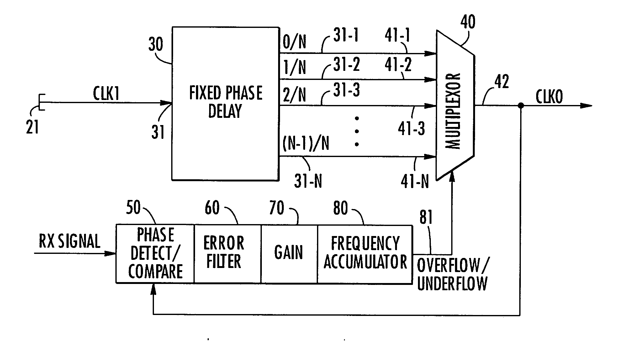
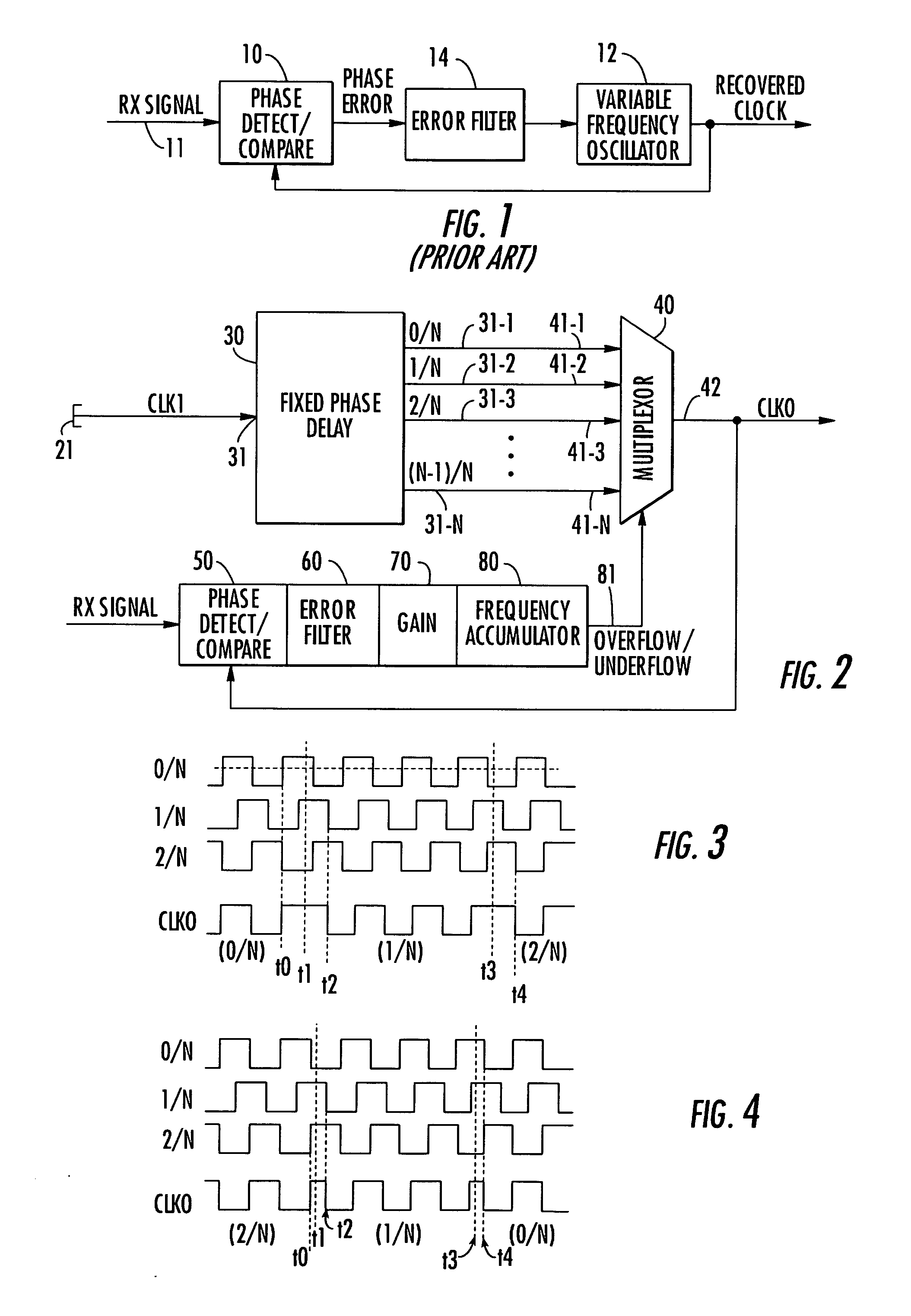
[0006] Where the output clock is running faster than the received signal, the state of the accumulator will cause the multiplexer to incrementally advance or step in a first, increased delay direction through the plurality of output ports of the delay line. This has the effect of lengthening a portion of one of the half-cycles of the output / recovered clock signal, thereby slowing down the recovered clock. On the other hand, where the output clock is running slower than the received signal, the state of the accumulator will cause the multiplexer to incrementally step through the output ports of the delay line in a reverse direction. This has the effect of shortening a portion of one of the half-cycles of the output / recovered clock signal, thereby speeding up the recovered clock.

Problems solved by technology

A shortcoming of this type of clock recovery scheme is the sensitivity and expense of the variable frequency oscillator, which is typically a crystal-based component, whose parameters may vary depending upon its manufacturer.
In addition, where the receiver is employed in a relatively harsh environment, the oscillator is prone to substantial operational variation and degradation.

Method used


Image

  • Digital clock recovery circuit employing fixed clock oscillator driving fractional delay line
  • Digital clock recovery circuit employing fixed clock oscillator driving fractional delay line

Examples


Embodiment Construction

[0011] Before describing the fixed fractional delay line-based clock recovery circuit in accordance with the present invention, it should be observed that the invention resides primarily in a modular arrangement of conventional digital communication circuits and components. In a practical implementation that facilitates their being packaged in a hardware-efficient equipment configuration, these modular arrangements may be readily implemented as field programmable gate array (FPGA), or application specific integrated circuit (ASIC) chip sets.

[0012] Consequently, the configuration of such arrangements of circuits and components and the manner in which they are interfaced with other telecommunication equipment have, for the most part, been illustrated in the drawings by readily understandable block diagrams, and associated timing diagrams, which show only those specific details that are pertinent to the present invention, so as not to obscure the disclosure with details which will be ...


PUM


Abstract

A clock recovery scheme for a digital communication receiver has a fixed fractional delay line that is driven by a fixed frequency reference clock source, to provide a plurality of respectively offset phase delayed versions of the reference clock. A phase lock loop, to which the received signal is coupled, controllably steps through the phase delayed versions of the reference clock, so as to controllably increase or decrease the effective frequency of the reference clock and thereby produce a recovered clock signal.

Description

FIELD OF THE INVENTION [0001] The present invention relates in general to communication systems and subsystems therefor, and is particularly directed to a clock recovery scheme for a digital communication receiver. The clock recovery scheme employs a fixed fractional delay line that is driven by a fixed reference clock source, to provide a plurality of respectively offset phase delayed versions of the reference clock. One of the phase delayed versions of the reference clock is used as the recovered clock. A control loop steps through the outputs of the fixed fractional delay line, so as to controllably increase or decrease the effective frequency of the reference clock and thereby adjust the frequency of the recovered clock signal. BACKGROUND OF THE INVENTION [0002] In order to successfully coherently recover data from a received digital communication signal, digital communication receivers employ some form of clock recovery or extraction mechanism that operates on the received sign...

Claims


Application Information

Patent Timeline
IPC IPC(8): H03L7/081H03L7/10H04L7/033
CPCH03L7/0814H04L7/0037H04L7/0337H03L7/10
Inventor KLIESNER, MATTHEW A.MESTER, TIMOTHY G.RIVES, ERIC M.
Owner ADTRAN
Learn More