
Multi-band single-carrier modulation

a single-carrier modulation and multi-band technology, applied in the field of communication systems, can solve the problems of ineffective implementation, inability to operate independently, and loss of data, and achieve the effect of reducing the number of incoming signals, and avoiding the loss of data

Inactive Publication Date: 2005-01-20
AVAGO TECH INT SALES PTE LTD
View PDF6 Cites 55 Cited by
  • Summary
  • Abstract
  • Description
  • Claims
  • Application Information

AI Technical Summary

Benefits of technology

[0039]FIG. 19 is a diagram illustrating another embodiment of a piconet operable device that supports functionality of interference compensation cap...

Problems solved by technology

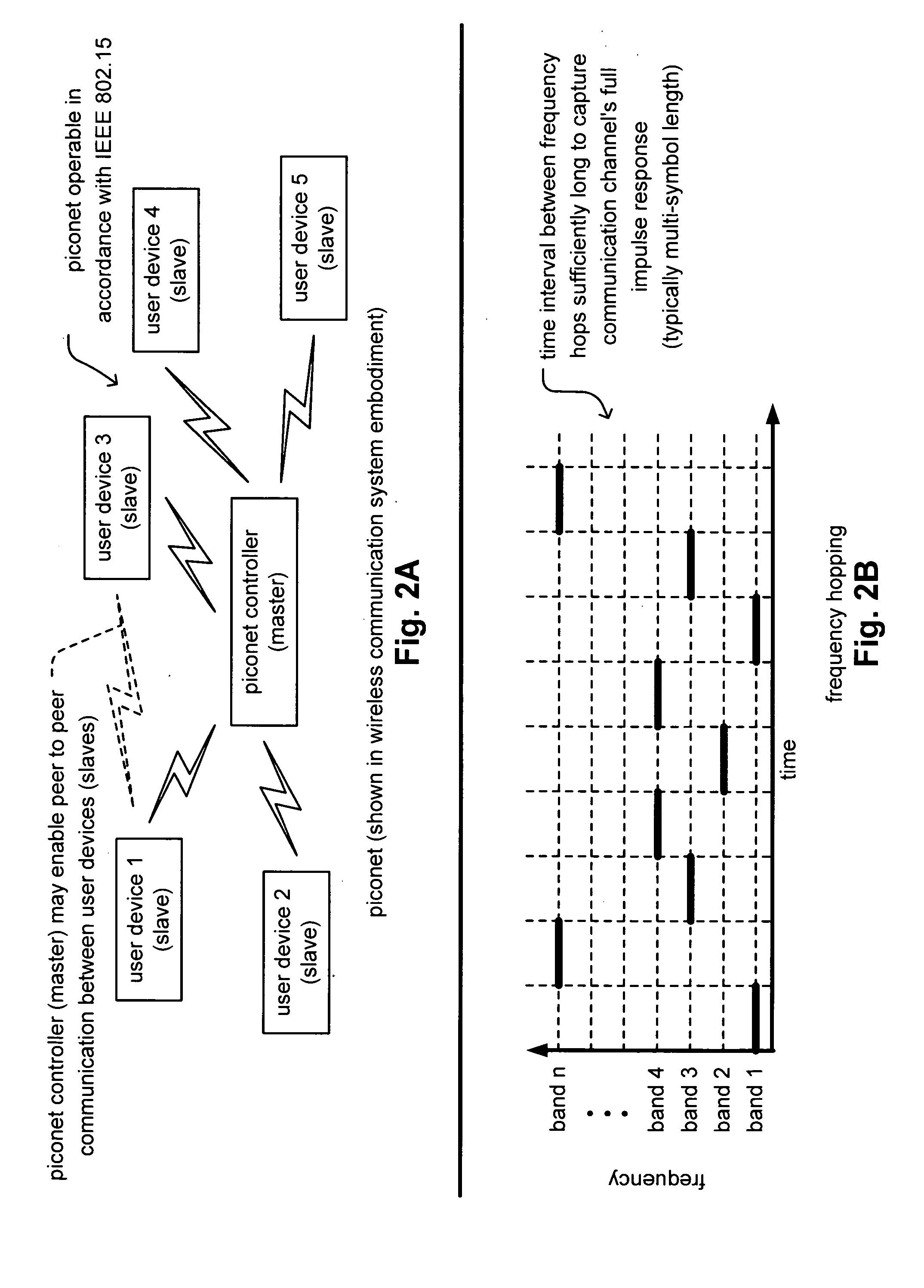
However, within a scatternet implementation, a problem may arise such that each of the individual piconets must be able to operate in relative close proximity with other piconets without interfering with one another.
It is also noted that independently operating piconets, not implemented within a scatternet implementation, may also suffer from deleterious effects of interference with other piconets located within relative close proximity.
One such deleterious effect that may arise is when the symbols (or pulses) being transmitted within the piconets operating within relatively close proximity collide with one another thereby resulting in potentially lost data.
Currently, there does not exist in the art a sufficient solution that may accommodate the undesirable effects of symbol collisions within such piconets in a satisfactory manner.
While there have been some attempts to try to deal with minimizing these undesirable symbol collisions within such piconets, there does not yet exist a satisfactory manner in which symbol collisions (when they do in fact occur) may be dealt with while maintaining a very high level of performance for all of the devices within the piconet.

Method used


Image

  • Multi-band single-carrier modulation
  • Multi-band single-carrier modulation
  • Multi-band single-carrier modulation

Examples


Embodiment Construction

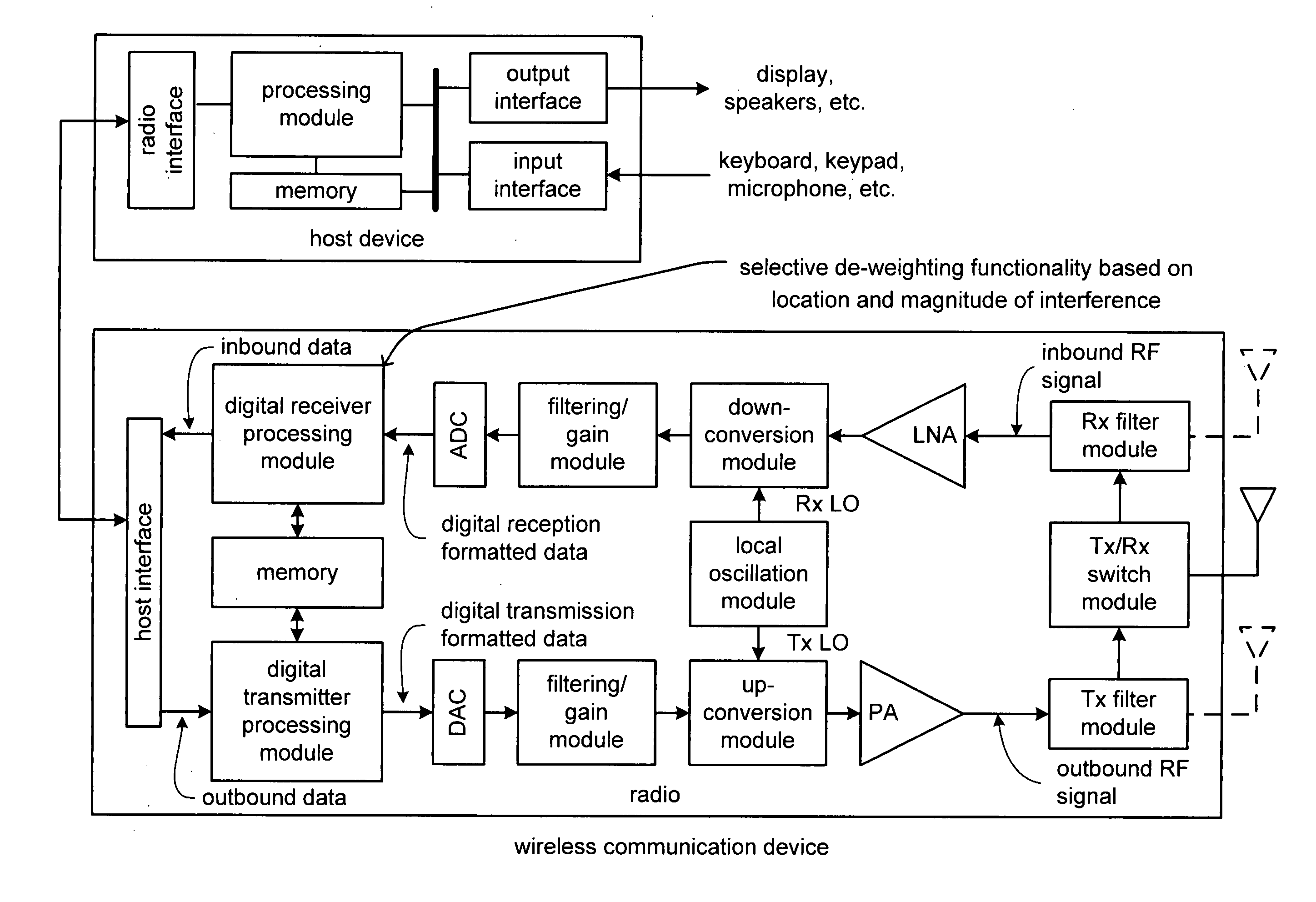
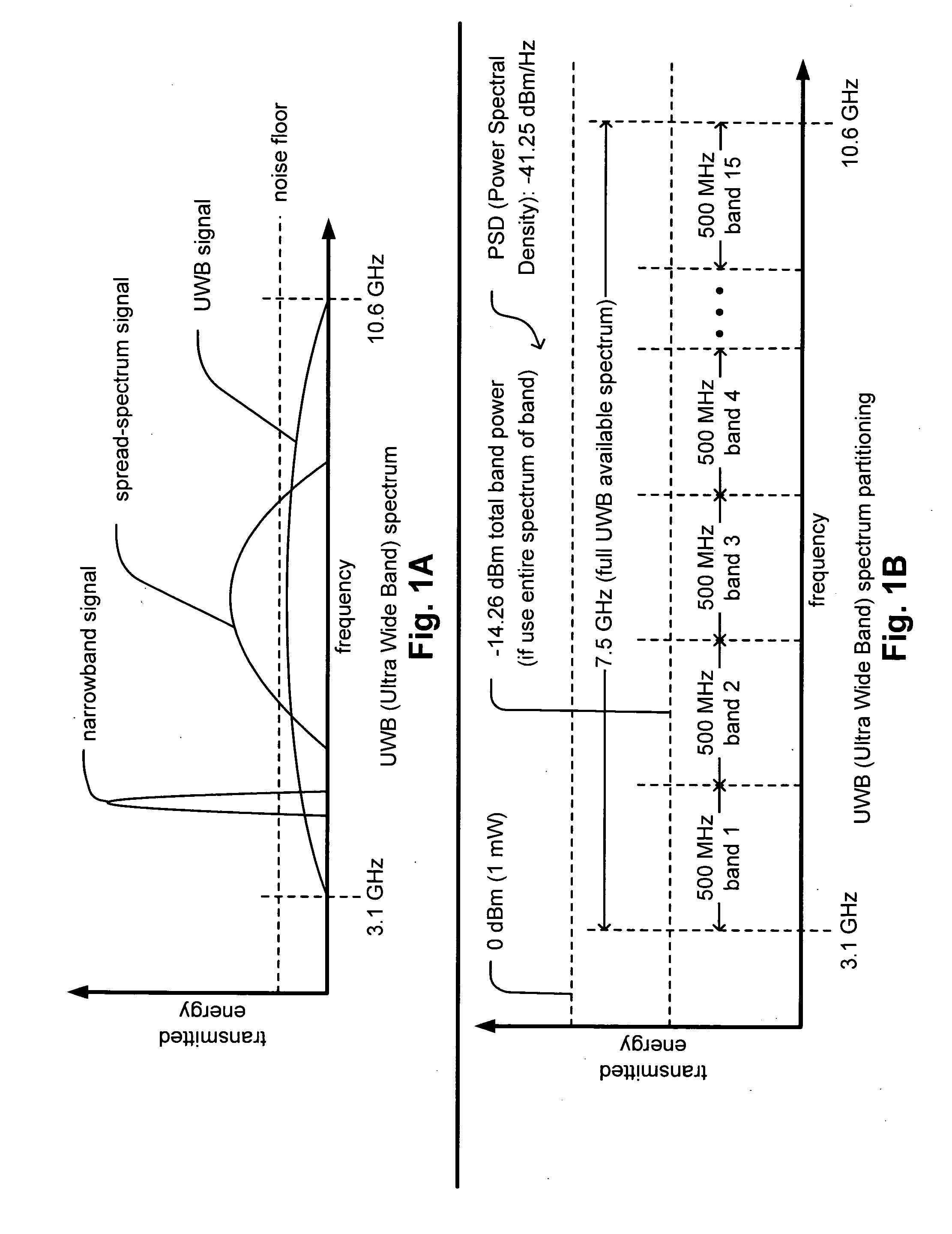
[0042] A novel approach is presented herein by which a piconet, or SOPs (Simultaneously Operating Piconets), may operate in such a manner as to have a minimal amount (if any) of interference between them. A single carrier (e.g., single carrier frequency) solution is provided in place of an OFDM (Orthogonal Frequency Division Multiplexing) solution. A piconet operable device is presented to include intelligence (e.g., smart receiver structure within the piconet operable device) that is able to perform estimation of the location and level (e.g., magnitude) of the interference and to perform appropriate processing to minimize its impact when demodulating and decoding a received signal. For example, this may involve selectively de-weighting only specific bits of one or more individual symbols of the received and demodulated signal.

[0043] Some background information is initially provided below to acquaint the reader to the particular context of operation of piconet and their use of the ...


PUM


Abstract

Multi-band single-carrier modulation. A novel approach is presented by which interference compensation may be performed for signals received by a piconet operable device. The piconet operable device may be implemented within a region that includes two or more SOPs (Simultaneously Operating Piconets). Estimation of the level and location of interference is performed and the input to a decoder (within the piconet operable device) is selectively weighted to ensure that the effect of any existent interference within the signal received by the piconet operable device is minimized. Different interference levels are dealt with differently. For one example, portions of the received signal having undergone a large amount of interference may be simply treated as erasures with respect to the input the decoder. For another example, portions of the received signal having undergone some smaller degree of interference, but some interference nonetheless, may be de-weighted before being provided to the decoder.

Description

CROSS REFERENCE TO RELATED PATENTS / PATENT APPLICATIONS [0001] The present U.S. Utility Patent Application claims priority pursuant to 35 U.S.C. § 119(e) to the following U.S. Provisional Patent Applications which are hereby incorporated herein by reference in their entirety and made part of the present U.S. Utility Patent Application for all purposes: [0002] 1. U.S. Provisional Application Ser. No. 60 / 488,623, entitled “UWB (Ultra Wide Band) interference mitigation,” (Attorney Docket No. BP3085), filed Jul. 18, 2003 (Jul. 18, 2003), pending. [0003] 2. U.S. Provisional Application Ser. No. 60 / 494,498, entitled “Multi-band single-carrier modulation,” (Attorney Docket No. BP3135), filed Aug. 12, 2003 (Aug. 12, 2003), pending.BACKGROUND OF THE INVENTION [0004] 1. Technical Field [0005] The invention relates generally to communication systems; and, more particularly, it relates to receive processing (demodulation and decoding) of signals received within such communication systems. [0006]...

Claims


Application Information

Patent Timeline
IPC IPC(8): H04B1/69H04L27/26
CPCH04B1/71637H04L27/2601H04B1/719
Inventor OJARD, ERIC J.
Owner AVAGO TECH INT SALES PTE LTD
Learn More