
Virtual MIMO transmitters, receivers, systems and methods

a transmitter and receiver technology, applied in the field of mimo (multiple input, multiple output) transmitters and receivers, systems and methods, can solve the problems of inability to distinguish the m/sub>t/sub>individual transmitted signals from one another, lack of convincing proof of the proposed theories, and inability to achieve the effect of promising approaches

Inactive Publication Date: 2005-01-13
NORTEL NETWORKS LTD
View PDF9 Cites 104 Cited by
  • Summary
  • Abstract
  • Description
  • Claims
  • Application Information

AI Technical Summary

Benefits of technology

In some embodiments, there are less than N receive antennas.

Problems solved by technology

However, the theories proposed thus far have been lacking of convincing proofs and / or are based upon a misleading assumption.
Unfortunately, this promising approach only works if the MT original signals can be separated from the MR received signals.
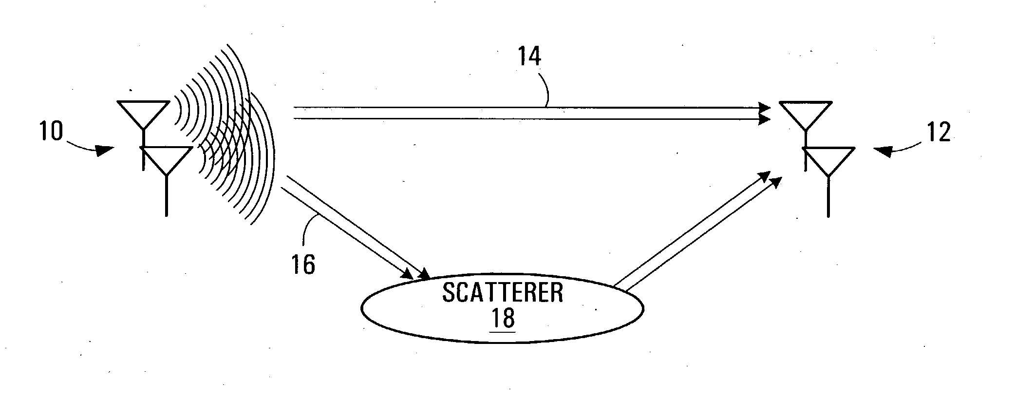
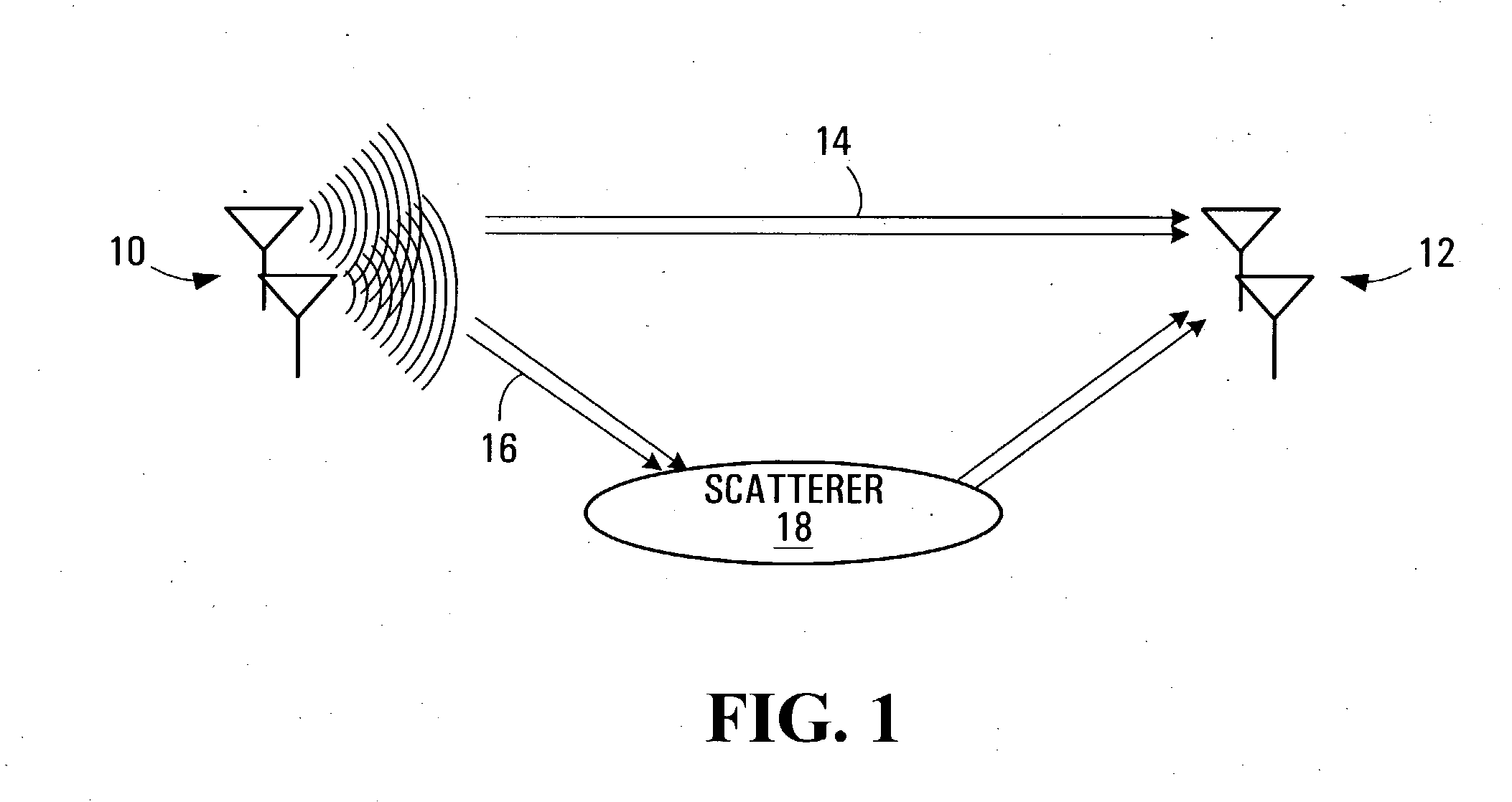
The problem here is that, in some practical scenarios, all MR antennas in the receiving antenna array receive essentially the same combination of the MT different transmitted signals (up to a global phase shift).
It is then extremely difficult if not impossible to distinguish the MT individual transmitted signals from one another.
Thus, if λLR>>LT / d, which is almost always true for cell-phone systems, it is impossible for the receiver to resolve the individual transmitted signals.
When the number of receiving antennas is less than the number of independent data transmission chains, the MIMO service cannot always be guaranteed.
This practical limitation makes it difficult to apply MIMO technology to terminal designs because one RF (radio frequency) chain contributes a significant part of the whole terminal cost, and multiple RF chains will result in too large of an expense.
Particularly, most of the wireless terminals on the market, if not all of them, have a single receiving antenna which means that the MIMO technology cannot be applied to these wireless terminals including TDMA, CDMA, WCDMA, 802.11 a / b and 802.16 etc.

Method used


Image

  • Virtual MIMO transmitters, receivers, systems and methods
  • Virtual MIMO transmitters, receivers, systems and methods
  • Virtual MIMO transmitters, receivers, systems and methods

Examples


embodiment

Multiple Receiver Embodiment

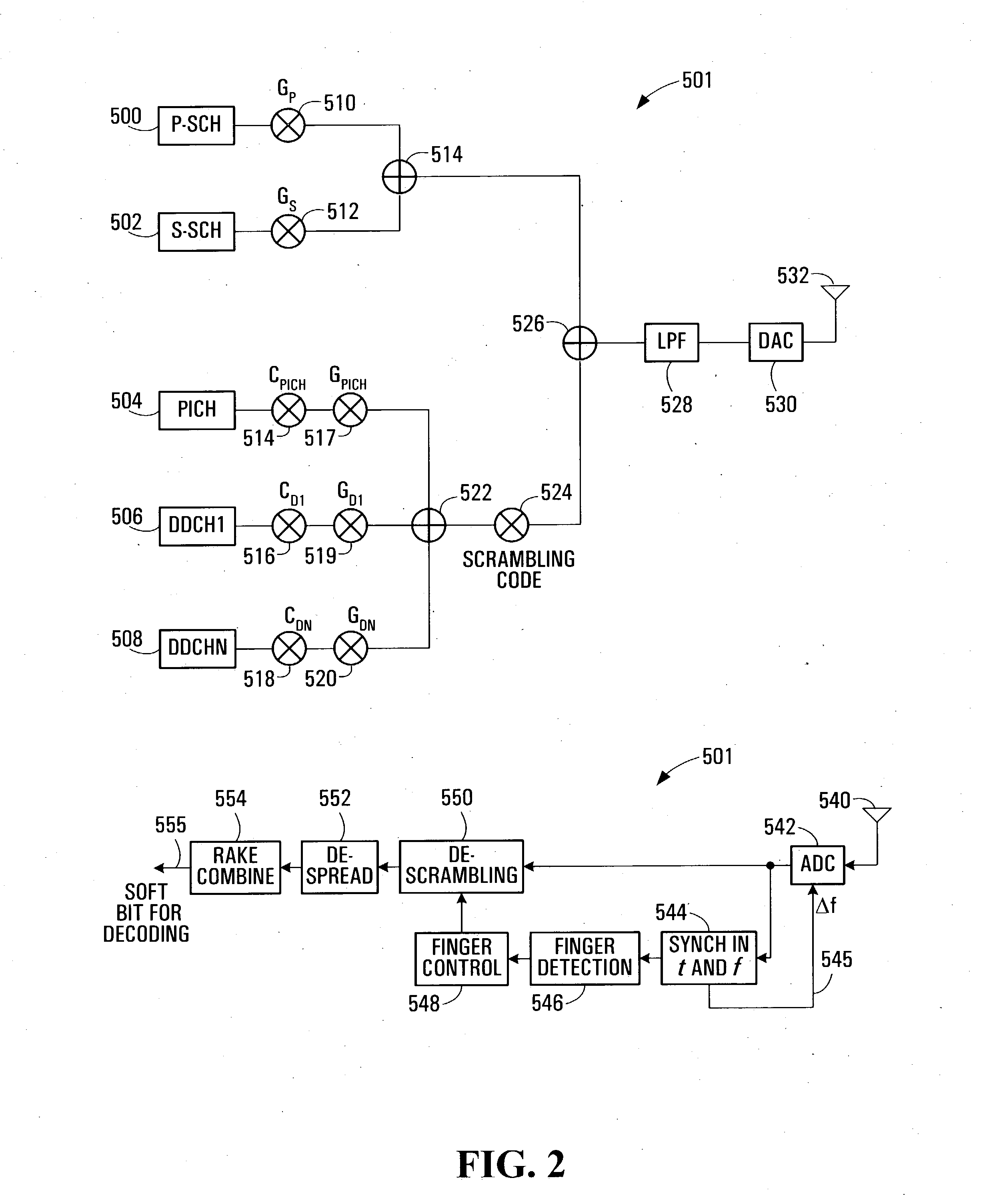
In the previous section, only multiple transmitter and single receiver systems have been discussed. However, more generally, embodiments can be used either in single receiver antenna systems or multiple receiver antennae system. In fact, the technology can be fully exploited in MIMO systems to produce a robust transceiver system while maintaining a low cost. For example, 2×4 MIMO system performance can be achieved with 2×2 MIMO systems with the invented technology built in. FIG. 14 illustrates a 2×2 MIMO receiver diagram provided by an embodiment of the invention that has similar performance to a MIMO 2×4 system.

Two antennae 400,402 are used to receive the incoming signals. A RF receiver 404 accepts the signal from antenna 400 and from there it proceeds to the ADC 406. The stream is split into even and odd paths with sample collector 408 and then framed 410 before undergoing prefix treatment 412,416. The processing done in combining the received signal...


PUM


Abstract

A system for doing BLAST with fewer receive antennas or even only one receiving antenna is provided. A system implementation architecture is provided together with a detailed analysis on its principle and theory behind this engineering solution to reduce the MIMO technology cost by using fewer antennas whilst achieving high spectrum efficiency. Examples are provided on how to implement this idea in a CDMA platform and in a OFDM platform. For the CDMA system, the code space is automatically doubled or tripled and therefore a significant system capacity increase is realized. For OFDM systems, the throughput is doubled similar as 2×2 blasting. The system complexity is minimum and full standards backward compatibility can be achieved.

Description

FIELD OF THE INVENTION The invention relates to MIMO (multiple input, multiple output) transmitters and receivers, systems and methods, and more specifically to such systems designed to have fewer antennas or only one antenna in the receiver. BACKGROUND OF THE INVENTION Over the past decade, there has been a revolution in the ways in which we communicate. The Internet has created the demand for high information transfer rates, while cell phones and other mobile wireless devices have fueled the desire for ubiquitous connectivity. A significant hurdle on the road toward achieving high data rate transmission is the limit on the amount of reliable information exchange between two ends, which is known as the channel capacity C. Channel capacity is the maximum value of the so called mutual information between the transmitter and the receiver that is given by Claude Shannon's famous formula: C=W⁢ ⁢log⁡(1+SW×No) or a normalized version C=log2⁡(1+SN)⁢ ⁢bps⁢ / ⁢Hz(1) where, S is the receive...

Claims


Application Information

Patent Timeline
Patent Type & Authority Applications(United States)
IPC IPC(8): H04B7/04H04B7/06H04L1/06H04L27/26
CPCH04B7/0413H04B7/0669H04L27/2647H04L1/0656H04L27/2626H04B7/0697
Inventor WU, SHIQUANTONG, WENROYER, CLAUDEZHU, PEIYING
Owner NORTEL NETWORKS LTD
Learn More