
Climate control for a greenhouse

a greenhouse and climate control technology, applied in the field of greenhouse climate control, can solve the problems of complex and expensive climate control systems for controlling air quality, and require additional design effor

Inactive Publication Date: 2005-01-13
CONTROLLED ENVIRONMENTS
View PDF3 Cites 25 Cited by
  • Summary
  • Abstract
  • Description
  • Claims
  • Application Information

AI Technical Summary

Benefits of technology

"The present invention provides an improved climate control system for greenhouses that uses a bench for supporting crop materials and an air handling system for conditioning the air. The system includes an air intake plenum, a fan, an outlet duct, and at least one air conditioning component for conditioning the air. The plenum has at least two inlets and each inlet has a cooling coil for cooling the air. The system is designed to control the air temperature, humidity, and air flow within the greenhouse. The technical effects of the invention include improved control of the greenhouse climate, increased efficiency of the air conditioning system, and reduced energy consumption."

Problems solved by technology

Greenhouses used for research and high value production often include complex and expensive climate control systems for controlling air quality including temperature control by heating and cooling as required, and humidity, by de-humidification and humidification as required.
However the benches for supporting the plants, the air handling system and the remaining components are not necessarily manufactured so as to best fit within the exterior structure.
Thus additional design effort is necessary to design and construct each of the separate components to match the structure of the exterior.

Method used


Image

  • Climate control for a greenhouse
  • Climate control for a greenhouse
  • Climate control for a greenhouse

Examples


Embodiment Construction

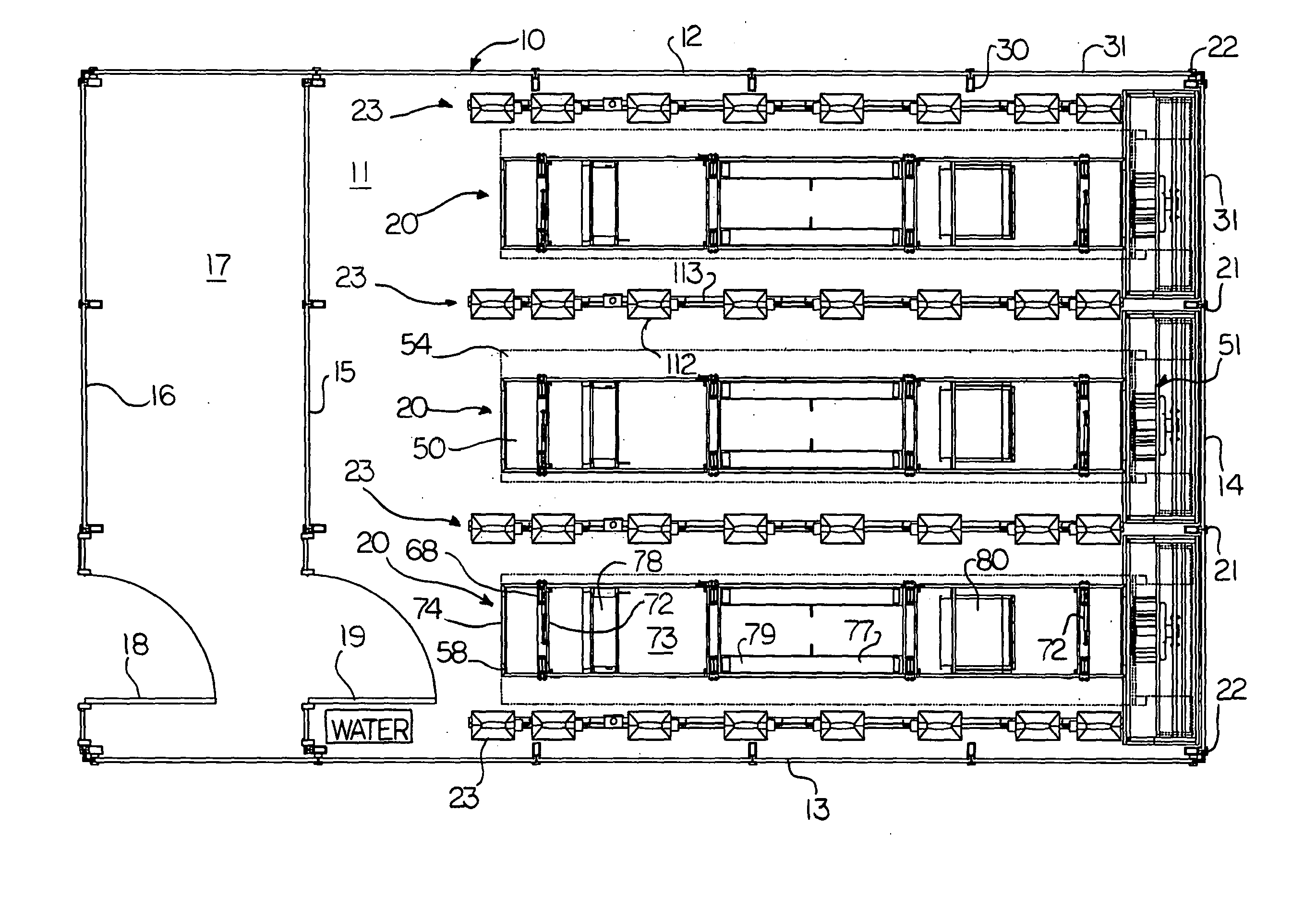
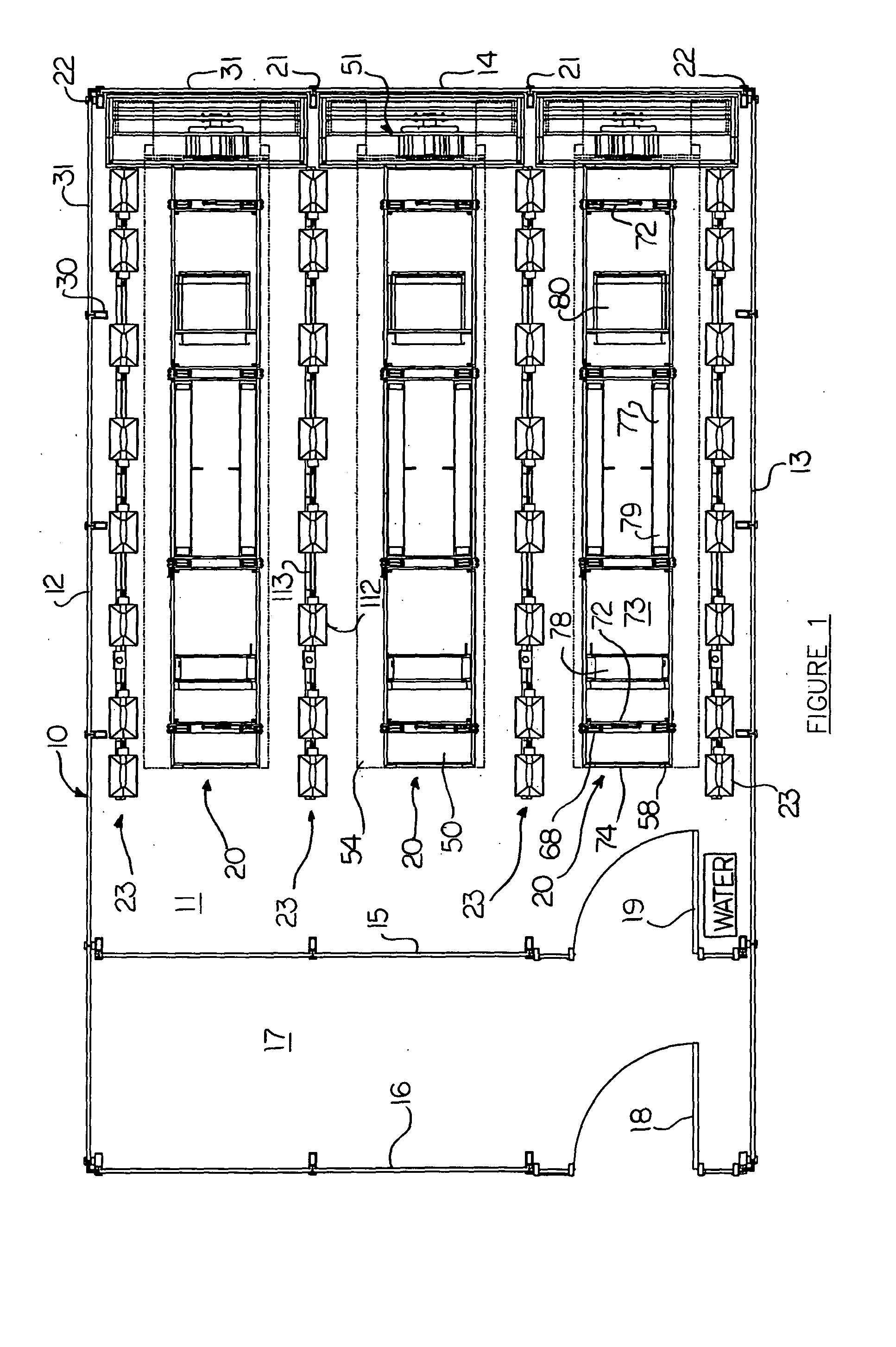
[0091] A greenhouse structure is shown in FIG. 1 and comprises an exterior wall 10 supported on a suitable concrete foundation 11 and defining side walls 12 and 13 of the greenhouse together with a first end wall 14 and a second end wall 15. Parallel to the end wall 15 is provided an alley wall 16 so that between the parallel walls 15 and 16 is an alleyway 17. A first door 18 allows access into the alley and is provided in wall 16 and a second door 19 is mounted in the wall 15 so as to allow access from the alley into the main interior of the greenhouse.

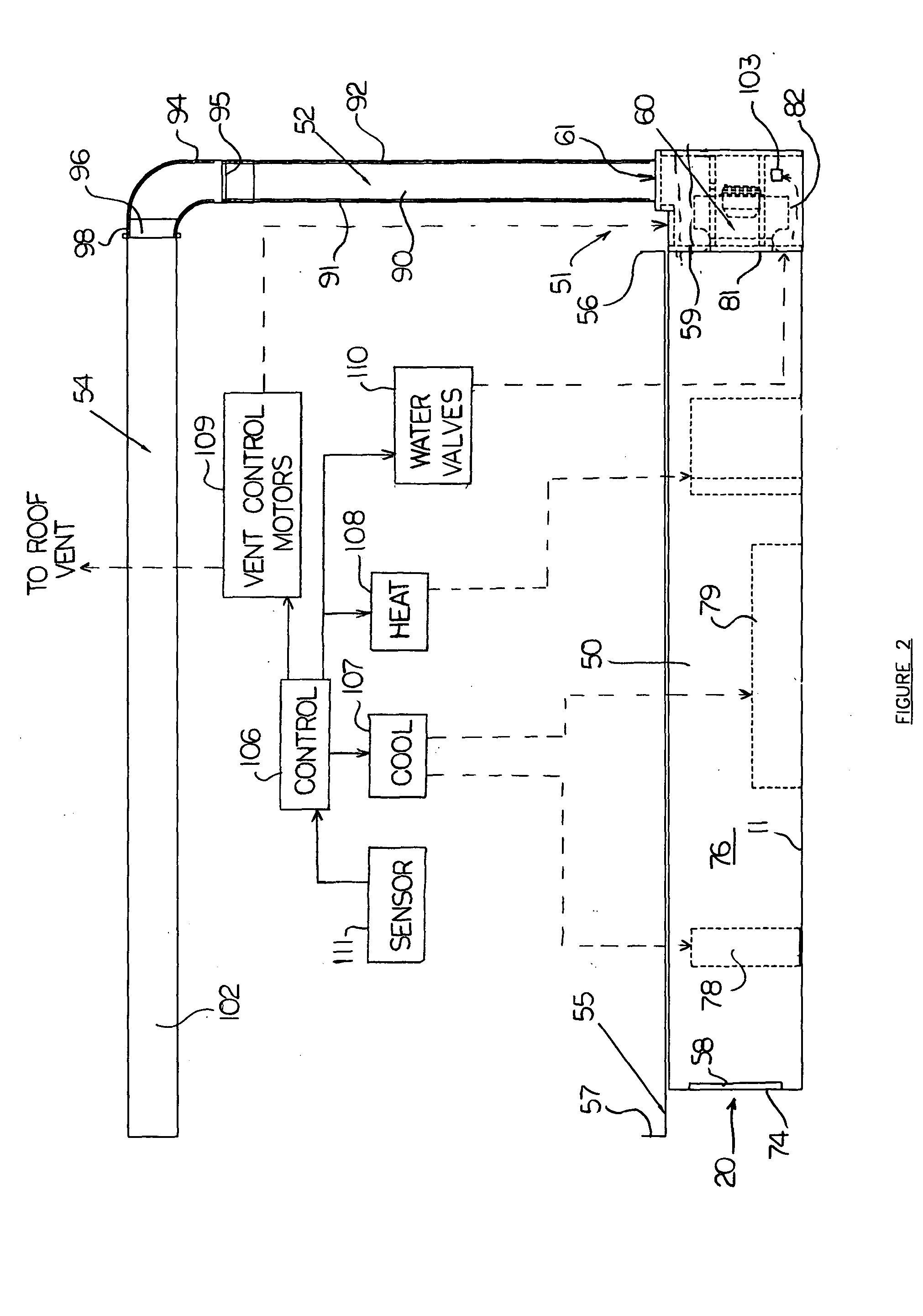
[0092] Within the greenhouse is mounted a plurality of greenhouse benches generally indicated at 20, each of which comprises an air handling system and a bench top support for plants. The greenhouse is manufactured as an expandable system so that the number of benches to be contained within the greenhouse can be increased or decreased in accordance with requirements by selecting a desired length of the greenhouse to accommodate an a...


PUM


Abstract

A greenhouse has an exterior curtain wall structure formed by spaced tubular posts carrying external transparent panels and bottom non-transparent wall panels below a sill with the panels spanning the posts. A plurality of elongate benches is located within the interior at spaced positions along one side wall with the width of the benches being equal to the post spacing to form an expandable construction. Each bench has associated with it a respective air handling system for conditioning including a duct which is located partly under the respective bench and a fan in a fan housing at the side wall. From the fan a vertical duct section extends to a flexible tube extending over the bench. Air dehumidification, fogging, heating and cooling are provided in the duct under the bench. An alley is arranged along the opposite wall containing electrical controls mounted in cabinets forming panels for mounting in the span between posts.

Description

[0001] This invention relates to a climate control system for a greenhouse. [0002] The term greenhouse as used herein is intended to be primarily but not exclusively directed to environmentally controlled growth chambers using primarily natural light and thus having transparent walls, and particularly to such structures having uniform and accurate control of the interior environment. Such structures are primarily intended for use in research or other similar environments where uniform and accurate control is of high importance rather than in crop production facilities where such close control of the environment cannot be economically justified. However the present invention is not intended to be limited to any particular type or use of such a facility. [0003] This application is related to a series of two further applications all filed simultaneously with this application and assigned to the same assignee as follows: [0004] Application Ser. No. INSERT filed INSERT and entitled Light...

Claims


Application Information

Patent Timeline
Patent Type & Authority Applications(United States)
IPC IPC(8): A01G9/24
CPCA01G9/246Y02A40/25
Inventor BRAULT, DAVIDTURKEWITSCH, ALEXGIERCKE, RONSCHRAM, STEVEZIMMERMAN, WAYNENORMANDIN, YVON
Owner CONTROLLED ENVIRONMENTS
Learn More