
Apparatus and method for coloring electric wire

a technology of electric wire and apparatus, which is applied in the manufacture of cables/conductors, coatings, basic electric elements, etc., can solve the problems of increasing the time period and labor hours required for the production of wires, deteriorating the yield of wire materials, and deteriorating the productivity of wires, so as to achieve a simple method of coloring. , the effect of simple structur

Inactive Publication Date: 2005-01-06
YAZAKI CORP
View PDF2 Cites 10 Cited by
  • Summary
  • Abstract
  • Description
  • Claims
  • Application Information

AI Technical Summary

Benefits of technology

[0014] Therefore, the objective of the present invention is to provide an apparatus having a simple structure and a simple method for coloring the outer surface of the wire, by which the area to be colored of the outer surface of the wire can be easily changed.
[0024] According to the present invention, the amount of the liquid drop of the coloring agent is increased or decreased depending on the pressure loss occurred when the coloring agent flows in the nozzle member. Therefore, the amount of the liquid drop of the coloring agent can be increased or decreased by selecting an appropriate coloring nozzle from a plurality of the coloring nozzles, which include the respective nozzle members having different length from one another, so as to spout the coloring agent. That is, by selecting an appropriate coloring nozzle, the area of a portion where the coloring agent adhere to, i.e. the area to be colored can be varied. Accordingly, the area to be colored can be easily varied with a simple construction in which a plurality of the coloring nozzles including the respective nozzle members having different lengths from one another are provided.
[0032] With the construction described above, the amount of the liquid drop of the coloring agent spouted from the long nozzle member is smaller than that spouted from the short nozzle member. The amount of the liquid drop of the coloring agent is increased or decreased depending on the pressure loss occurred when the coloring agent flows in the nozzle member. Therefore, the amount of the liquid drop of the coloring agent can be increased or decreased by selecting an appropriate coloring nozzle from a plurality of the coloring nozzles, which include the respective nozzle members having different length from one another, so as to spout the coloring agent. That is, by selecting an appropriate coloring nozzle, the area of a portion where the coloring agent adhere to, i.e. the area to be colored can be varied. Accordingly, the area to be colored can be easily varied by a simple method, in which the coloring agent is spouted from the appropriate coloring nozzle selected from a plurality of the coloring nozzles including the respective nozzle members having different lengths from one another.
[0038] With the construction described above, the amount of the liquid drop of the coloring agent spouted when the long second nozzle member is attached to the first nozzle member is smaller than that spouted when the short second nozzle member is attached to the first nozzle member. The amount of the liquid drop of the coloring agent is increased or decreased depending on the pressure loss occurred when the coloring agent flows in the second nozzle member and in the first nozzle member. Therefore, the amount of the liquid drop of the coloring agent can be increased or decreased by selecting an appropriate second nozzle member from a plurality of the second nozzle members having different length from one another so as to attach the selected second nozzle member to the first nozzle member. That is, by selecting an appropriate second nozzle member, the area of a portion where the coloring agent adhere to, i.e. the area to be colored can be varied. Accordingly, the area to be colored can be easily varied with a simple construction in which an appropriate second nozzle member is selected from a plurality of the second nozzle members having different length from one another so as to attach the selected second nozzle member to the first nozzle member.
[0044] With the construction described above, the amount of the liquid drop of the coloring agent spouted when the long second nozzle member is attached to the first nozzle member is smaller than that spouted when the short second nozzle member is attached to the first nozzle member. The amount of the liquid drop of the coloring agent is increased or decreased depending on the pressure loss occurred when the coloring agent flows in the second nozzle member and in the first nozzle member. Therefore, the amount of the liquid drop of the coloring agent can be increased or decreased by selecting an appropriate second nozzle member from a plurality of the second nozzle members having different length from one another so as to attach the selected second nozzle member to the first nozzle member. That is, by selecting an appropriate second nozzle member, the area of a portion where the coloring agent adhere to, i.e. the area to be colored can be varied. Accordingly, the area to be colored -can be easily varied by a simple method, in which an appropriate second nozzle member is selected from a plurality of the second nozzle members having different length from one another so as to attach the selected second nozzle member to the first nozzle member.

Problems solved by technology

That is, whenever the color of the wire is changed, it is necessary to halt an operation of an extrusion apparatus, causing increasing in a time period and labor hour required for the production of the wire and deteriorating in the productivity of the wire.
In such a case, right after changing the color of the coloring agent, a wire, in the color of the synthetic resin of which a coloring agent before the replacement and a coloring agent after the replacement are mixed, has been inevitably manufactured, causing the deterioration in the yield of the material of the wire.
However, in order to change such a pressure or such a time period, the coloring apparatus is forced to have a complicated mechanism therein, thereby causing an increasing in the cost of the coloring apparatus.

Method used


Image

  • Apparatus and method for coloring electric wire
  • Apparatus and method for coloring electric wire
  • Apparatus and method for coloring electric wire

Examples


Embodiment Construction

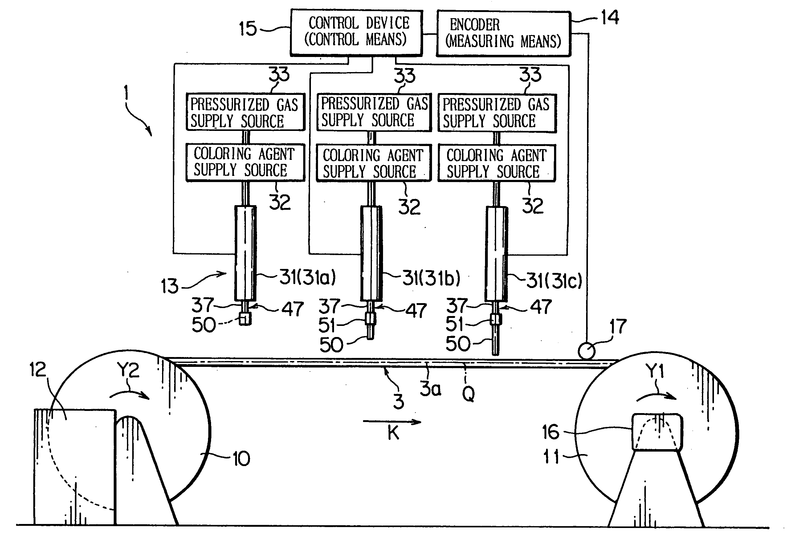
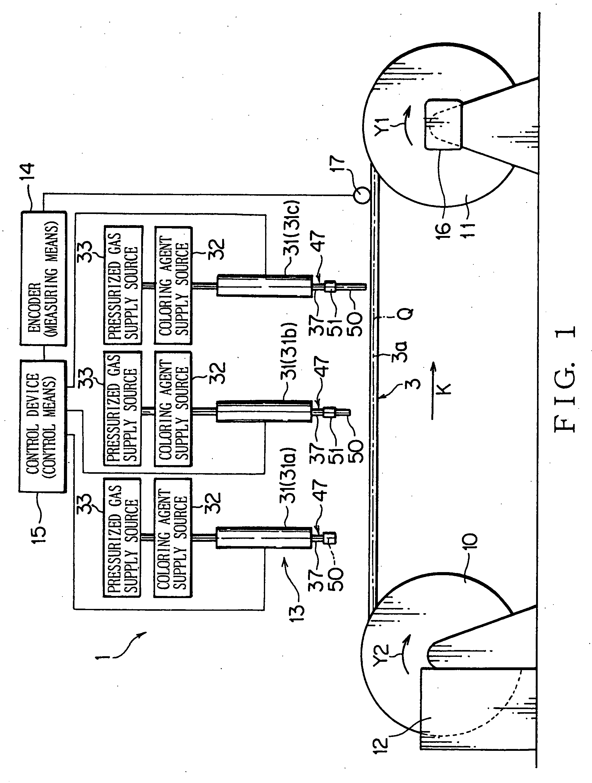
[0057] In the following, an apparatus 1 for coloring an electric wire (i.e. coloring apparatus 1) according to a first preferred embodiment of the present invention will be explained with reference to. FIGS. 1-6. The coloring apparatus 1 shown in FIG. 1 and so on is an apparatus for forming a mark 6 on a part of an outer surface 3a of an electric wire 3 (i.e. wire 3). That is, the coloring apparatus 1 colors the outer surface 3a of the wire 3, i.e. performs marking on the outer surface 3a of the wire 3.

[0058] An electric wire 3 constitutes a wiring harness to be mounted on a motor vehicle or the like as a mobile unit. As shown in FIG. 6A and so on, the wire 3 includes an electrically conductive core wire 4 and an electrically insulating coating 5. A plurality of element wires are bundled up to form the core wire 4. Each element wire of the core wire 4 is made of electrically conductive metal. The core wire 4 may be constituted by a single element wire. The coating 5 is made of synt...


PUM


Abstract

The apparatus for coloring a wire includes a plurality of coloring nozzles, each of which spouts a liquid coloring agent toward an outer surface of a wire with a specific amount thereof per spouting so as to allow the liquid drop of the coloring agent to adhere to the outer surface of the wire, thereby coloring the wire. The coloring agent adheres on the outer surface of the wire so as to form a spot. Each coloring nozzle includes an insert member for receiving the coloring agent therein and a nozzle member that communicates with the insert member. The length of the nozzle member is different from each other. The apparatus selects one coloring nozzle from a plurality of the coloring nozzles in response to the size of the spot to be formed on the outer surface of the wire and spouts the coloring agent.

Description

BACKGROUND OF THE INVENTION [0001] (1) Field of the Invention [0002] The present invention relates to an apparatus and method for coloring an electric wire that includes an electrically conductive core wire and an electrically insulating coating for coating the core wire. [0003] (2) Description of the Related Art [0004] Various electronic devices are mounted on a motor vehicle as a mobile unit. Therefore, the motor vehicle is provided with a wiring harness for transmitting power from a power source and control signals from a computer to the electronic devices. The wiring harness includes a plurality of electric wires and connectors attached to an end of the wires. [0005] The wire includes an electrically conductive core wire and a coating made of insulating synthetic resin, which coats the core wire. The wire is a so-called coated wire. A connector includes a terminal fitting and a connector housing that receives the terminal fitting therein. The terminal fitting, consisting of elec...

Claims


Application Information

Patent Timeline
IPC IPC(8): B05B1/14B05B15/04H01B13/34
CPCH01B13/345
Inventor KAMATA, TAKESHISUGIMURA, KEIGOSAITO, SEIYAGI, KIYOSHI
Owner YAZAKI CORP
Learn More