
Organic electroluminescent device and electronic apparatus

an electroluminescent device and electronic technology, applied in the direction of discharge tube luminescnet screens, discharge tube/lamp details, electric discharge lamps, etc., can solve the problems of difficult to improve the resolution, unsuitable for human visual system, application to organic electroluminescent devices, etc., to improve apparent resolution, improve the apparent resolution, and reduce the pitch among pixels

Active Publication Date: 2005-01-06
ELEMENT CAPITAL COMMERCIAL CO PTE LTD
View PDF4 Cites 105 Cited by
  • Summary
  • Abstract
  • Description
  • Claims
  • Application Information

AI Technical Summary

Benefits of technology

"The present invention provides an organic electroluminescent device with improved display resolution without significantly decreasing the pitches between pixels. The device includes a luminescent layer with dots consisting of red, green, and blue sub-pixels arranged in predetermined patterns. By forming each pixel with more than three sub-pixels, the apparent resolution is improved without significantly decreasing the pitches between pixels. The device can be easily formed in a similar manner to conventional stripe or mosaic patterns. The invention also provides an electronic apparatus including the organic electroluminescent device, which allows for excellent image display."

Problems solved by technology

However, in view of perception, it is not suitable for the human visual system to form each of the pixels so as to include the same quantities of red, green, and blue dots.
In the case of a pattern in which four dots (cells) are arranged in the substantially matrix pattern, for example, the quantity of the blue sub-pixels can be increased; however, it is difficult to improve the resolution since this arrangement is basically conceived to facilitate the drive control operation.
In recent years, organic electroluminescent displays have been remarkably developed; however, the application to organic electroluminescent devices is not considered in the above-mentioned technology.

Method used


Image

  • Organic electroluminescent device and electronic apparatus
  • Organic electroluminescent device and electronic apparatus
  • Organic electroluminescent device and electronic apparatus

Examples


Embodiment Construction

[0036] The present invention will be explained in detail below.

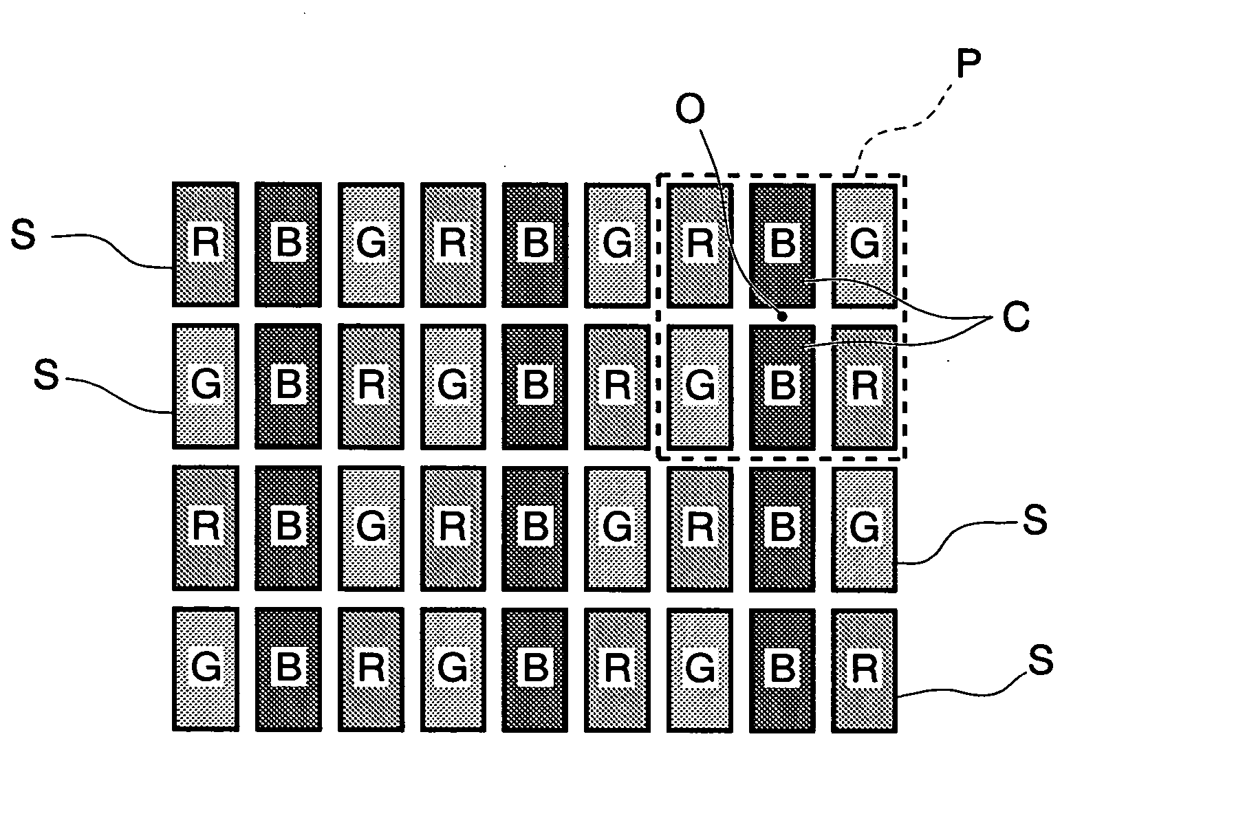
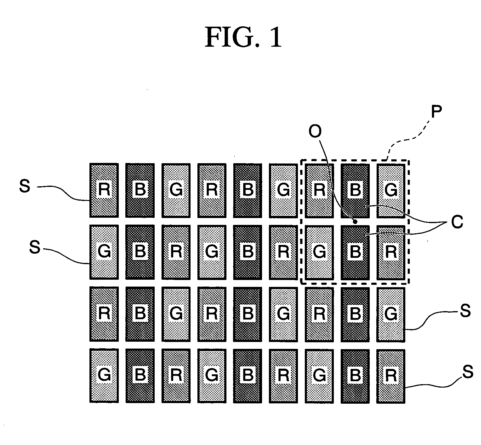
[0037]FIG. 1 is a diagram showing an embodiment of an organic electroluminescent device according to the present invention, and is a diagram showing arrangement pattern of sub-pixels in a luminescent layer. In FIG. 1, reference symbol S indicates sub-pixels which form dots in the luminescent layer. The sub-pixels S include three colored sub-pixels, i.e., red sub-pixels (indicated by “R” in FIG. 1, and hereinafter referred to as sub-pixels R), green sub-pixels (indicated by “G” in FIG. 1, and hereinafter referred to as sub-pixels G), and blue sub-pixels (indicated by “B” in FIG. 1, and hereinafter referred to as sub-pixels B).

[0038] These three colored sub-pixels S (R, G, and B) are formed as rectangles having the same size, and in this embodiment, each of arrangement patterns P includes six sub-pixels. The luminescent layer of this embodiment is formed by arranging the arrangement patterns P horizontally and vertically...


PUM


Abstract

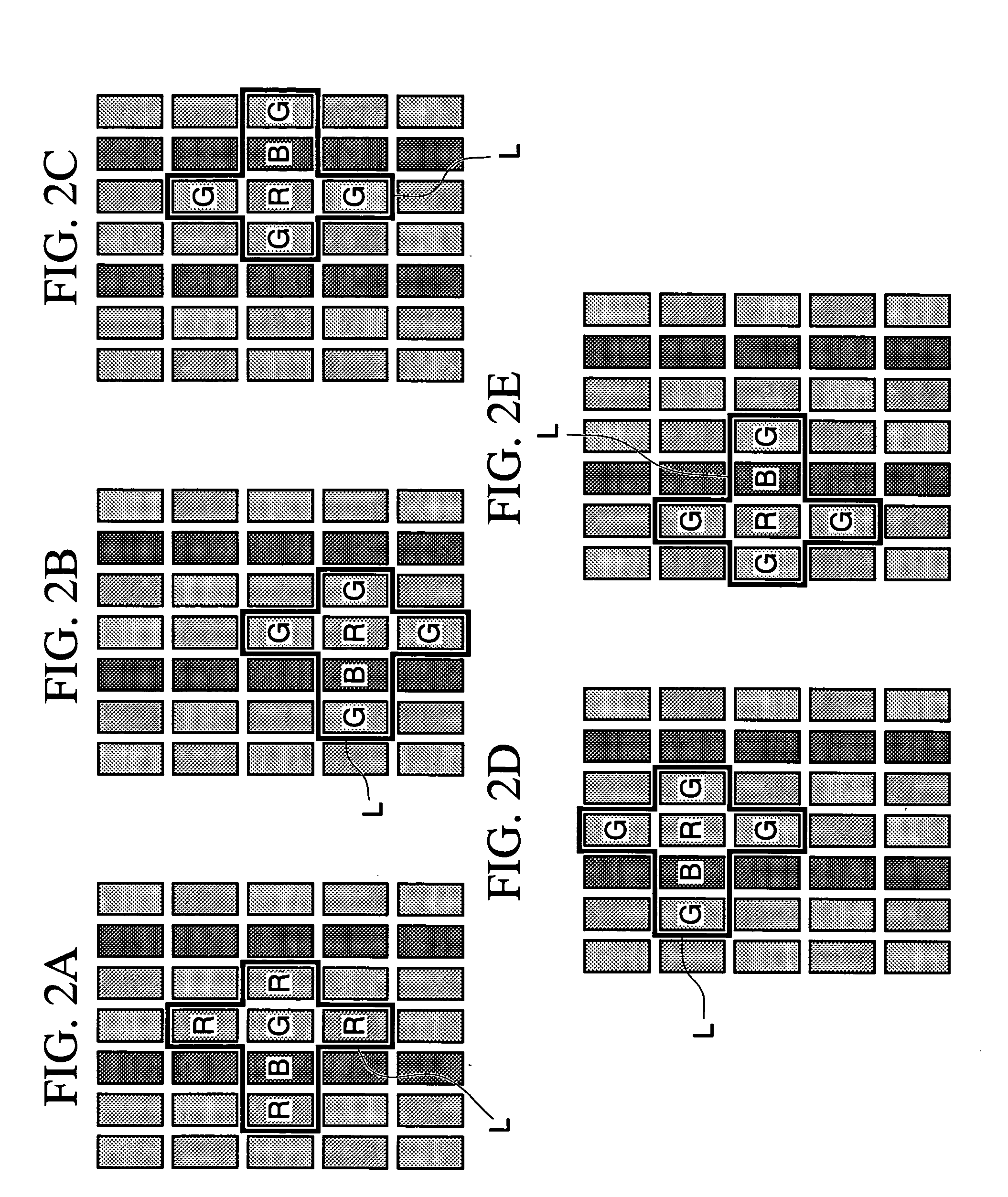
An organic electroluminescent device includes electrodes, a luminescent layer which is sandwiched between the electrodes, and which includes dots consisting of red sub-pixels, green sub-pixels, and blue sub-pixels. The sub-pixels are arranged in predetermined patterns, each of the predetermined patterns being formed such that at least one blue sub-pixel is disposed as a central pattern, the red sub-pixels are symmetrically arranged about a central point of the central pattern, and the green sub-pixels are also symmetrically arranged about the central point of the central pattern.

Description

BACKGROUND OF THE INVENTION [0001] 1. Field of the Invention [0002] The present invention relates to an organic electroluminescent device and to an electronic apparatus having the organic electroluminescent device. [0003] Priority is claimed on Japanese Patent Application No. 2003-126316, filed May 1, 2003, the content of which is incorporated herein by reference. [0004] 2. Description of Related Art [0005] Currently, display devices must be capable of displaying color images. In general, in order to display color images, plural sets of three kinds of dots, i.e., plural sets of red, green, and blue dots, which respectively emit red light (R), green light (G), and blue light (B), as minimum displaying units (sub-pixels), are used. These three kinds of dots form one pixel which is a minimum unit for color displaying. [0006] As arrangement patterns of such dots (sub-pixels) for forming pixels, a stripe pattern shown in FIG. 12A, a mosaic pattern shown in FIG. 12B, and a delta pattern s...

Claims


Application Information

Patent Timeline
Patent Type & Authority Applications(United States)
IPC IPC(8): H05B33/12H01L27/32H01L51/40H01L51/50H01L51/56
CPCH01L27/3211H01L51/56H01L51/0004H01L27/3244H10K59/352H10K71/13H10K59/12H05B33/12H10K71/00
Inventor KIGUCHI, HIROSHI
Owner ELEMENT CAPITAL COMMERCIAL CO PTE LTD
Learn More