
Sample analysis methodology utilizing electromagnetic radiation

a sample analysis and electromagnetic radiation technology, applied in the direction of optical radiation measurement, instruments, polarisation-affecting properties, etc., can solve the problem of difficult to identify content in spectroscopic data

Active Publication Date: 2004-12-23
J A WOOLLAM CO
View PDF1 Cites 25 Cited by
  • Summary
  • Abstract
  • Description
  • Claims
  • Application Information

AI Technical Summary

Benefits of technology

[0430] The method can further comprises saving the optical constants determined over the entire range of wavelengths or energy or wave number etc., and replacing the mathematical model of the thin layer with a mathematical model which allows fitting the refractive index or the imaginary part of the dielectric function with Mathematical Dispersion Models such as Kramers-Kronig consistent oscillators, plotting said refractive index or imaginary part of the dielectric function and fitting said refractive index or imaginary part of the dielectric function with at least one Mathematical Dispersion Model and performing a regression to evaluate parameters in said mathematical model.
[0576] Note that the just recited example can be benefically applied to the case where a MOSFET Gate metalization is being deposited to a substrate on which is present less than 100 Angstroms of Gate Oxide or other Gate insulator material. The Witness Sample, having a much thicker layer of Oxide or other Insulator, enables acquisition of a spectra which makes the detection of the thickness of the deposited metal much more pronounced. The effect is demonstrated graphically in the Detailed Description Section of this Specification, using Amorphous Silicon and Amorphous Carbon thin films on thick transparent dielectric.

Problems solved by technology

It is also disclosed that where investigated films are very thin, (eg. less than 100 Angstroms), it becomes difficult to identify content in spectroscopic data which is definitely correlated to thin film characterizing parameters, such as dielectric constant and / or thickness.

Method used


Image

  • Sample analysis methodology utilizing electromagnetic radiation
  • Sample analysis methodology utilizing electromagnetic radiation
  • Sample analysis methodology utilizing electromagnetic radiation

Examples


Embodiment Construction

of the J.A. Woollam Co GEMOSC.TM. Layer

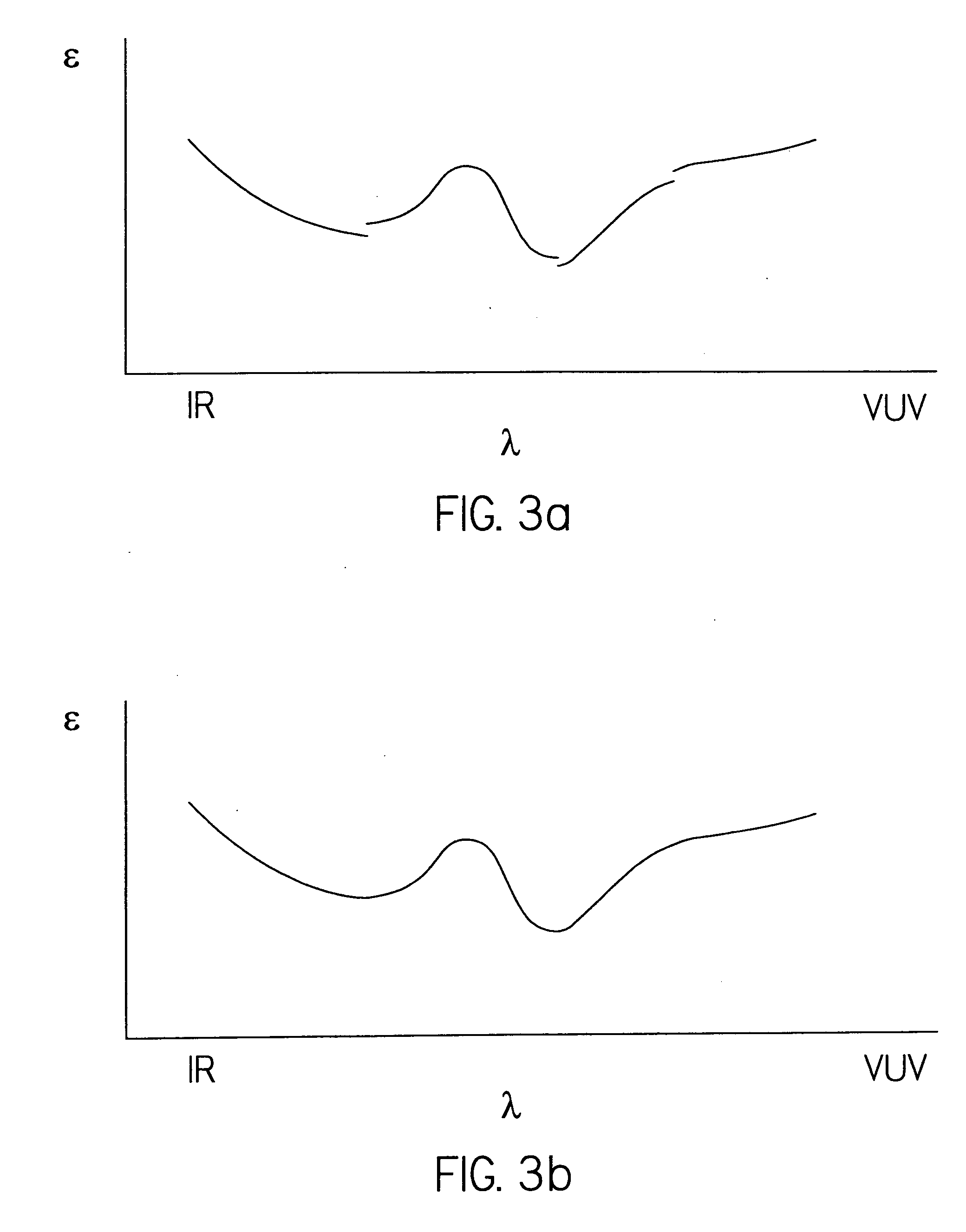
[0587] As an example of application of the J.A. Woollam CO. GEMOSC.TM. Layer, which was mentioned in the Disclosure Section of this Specification, the following simple Analysis of a SiNx film is presented. Generally, the GENOSC approach is applicable to analysis of thin films which are, transparent in one wavelength range and absorbing in another, (eg. transparent at visible wavelengths but demonstrating;significant absorption at UV wavelengths). The approach is applicable to modeling:

n(.lambda.)+ik(.lambda.)

e1(.lambda.)+ie2(.lambda.);

[0588] which expressions are mathematically identical In that light it is disclosed that amorphous SiNx films are often transparent in the near-infrared (NIR) and throughout the most of the visible (VIS) spectra. Above the Bandgap, the UV of the e2(.lambda.) curve often demonstrates broad bulging curvature as can be modeled by a Tauc-Lorentz Dispersion function.

[0589] The Analysis Strategy for applying the GENOSC ...


PUM


Abstract

Simultaneous use of wavelengths in at least two ranges selected from RADIO, MICRO, FIR, IR, NIR-VIS-NUV, UV, DUV, VUV EUV, XRAY in a regression procedure to evaluate parameters in mathematical dispersion structures to model dielectric functions.

Description

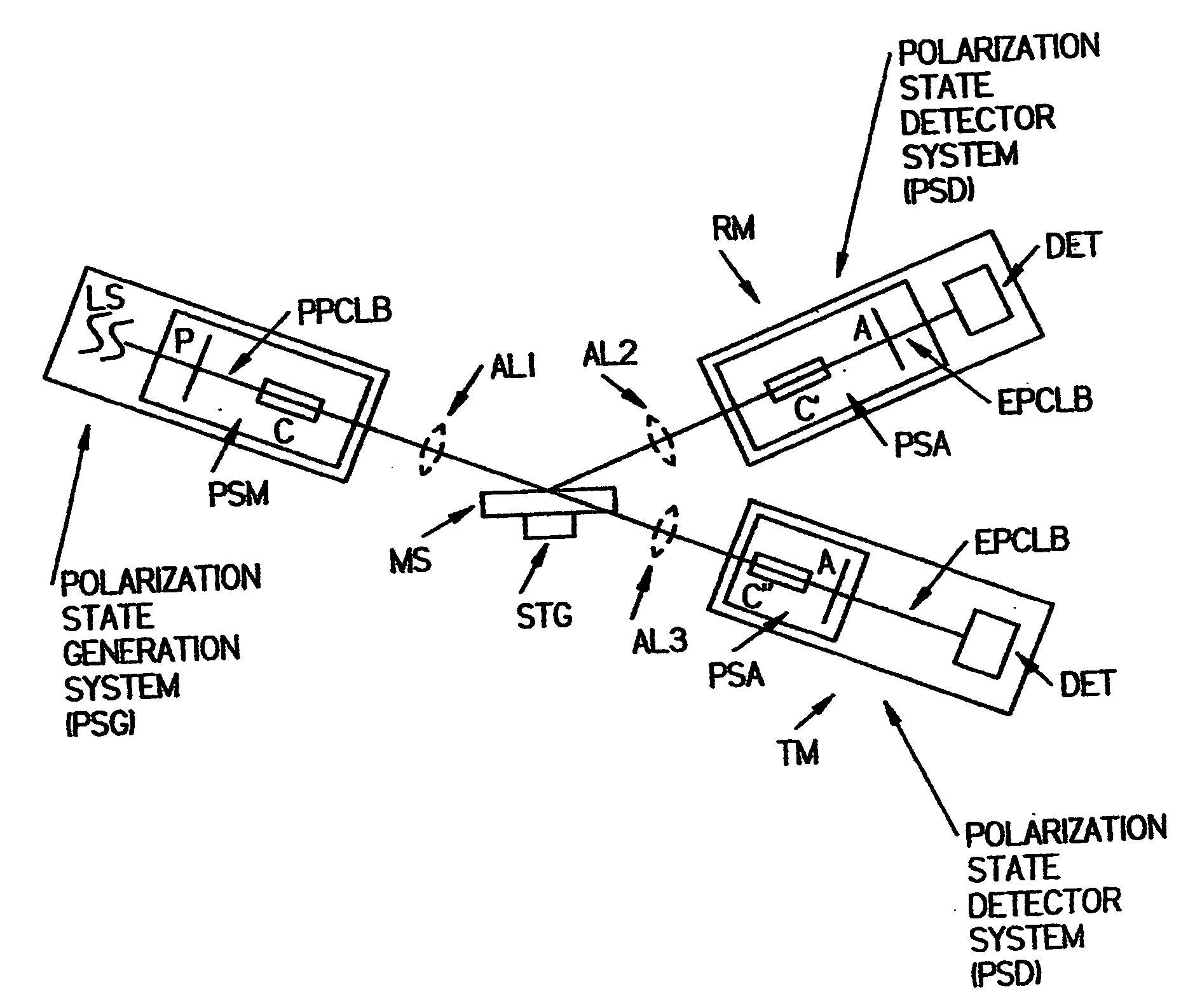
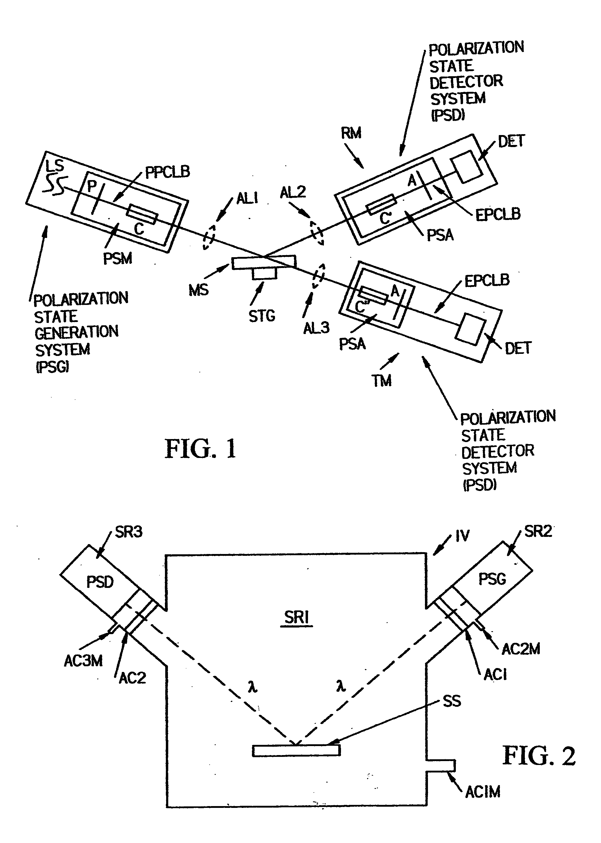
[0001] This Application is a CIP of Application 10 / 713,816 Filed Nov. 17, 2003 and Ser. No. 10 / 376,677 Filed Feb. 28, 2003; and Claims Benefit of Provisional Applications Ser. No. 60 / 471,769 Filed May 20, 2003, and 60 / 485,009 Filed Jul. 05, 2003, and 60 / 527,553 Filed Dec. 06. 2003.[0002] The disclosed invention relates to methodology for analysis of sample systems utilizing electromagnetic radiation; and more particularly to the simultaneous use of wavelengths in at least two ranges selected from RADIO, MICRO, FIR, IR, NIR-VIS-NUV, UV, DUV, VUV, EUV and XRAY in a regression procedure to evaluate parameters in mathematical dispersion relationships.[0003] It is well known to apply electromagnetic radiation to evaluate optical properties of sample systems. The disclosed invention can comprise any means for generating an electromagnetic beam and causing it to impinge upon a sample system, such as:[0004] reflectometer;[0005] spectrophotometer;[0006] ellipsometer;[0007] spectroscopic elli...

Claims


Application Information

Patent Timeline
IPC IPC(8): G01N21/21
CPCG01N21/211G01N2021/213
Inventor WOOLLAM, JOHN A.BUNGAY, COREY L.TIWALD, THOMAS E.LIPHARDT, MARTIN M.SYNOWICKI, RONALD A.PRIBIL, GREGORY K.HERZINGER, CRAIG M.JOHS, BLAINE D.HILFIKER, JAMES N.
Owner J A WOOLLAM CO
Learn More