
Method for producing a 3-D microscope flow-through cell

a flow-through cell and micro-scope technology, applied in the direction of labeling machines, material analysis, mechanical control devices, etc., can solve the problems of inability to accurately adjust the micro-sized channel to the structure of one or both cover glasses, limited channel geometry, and inability to fabricate internal channel barriers

Inactive Publication Date: 2004-12-16
GESIM GES FUR SILIZIUM MIKROSYST
View PDF3 Cites 17 Cited by
  • Summary
  • Abstract
  • Description
  • Claims
  • Application Information

AI Technical Summary

Benefits of technology

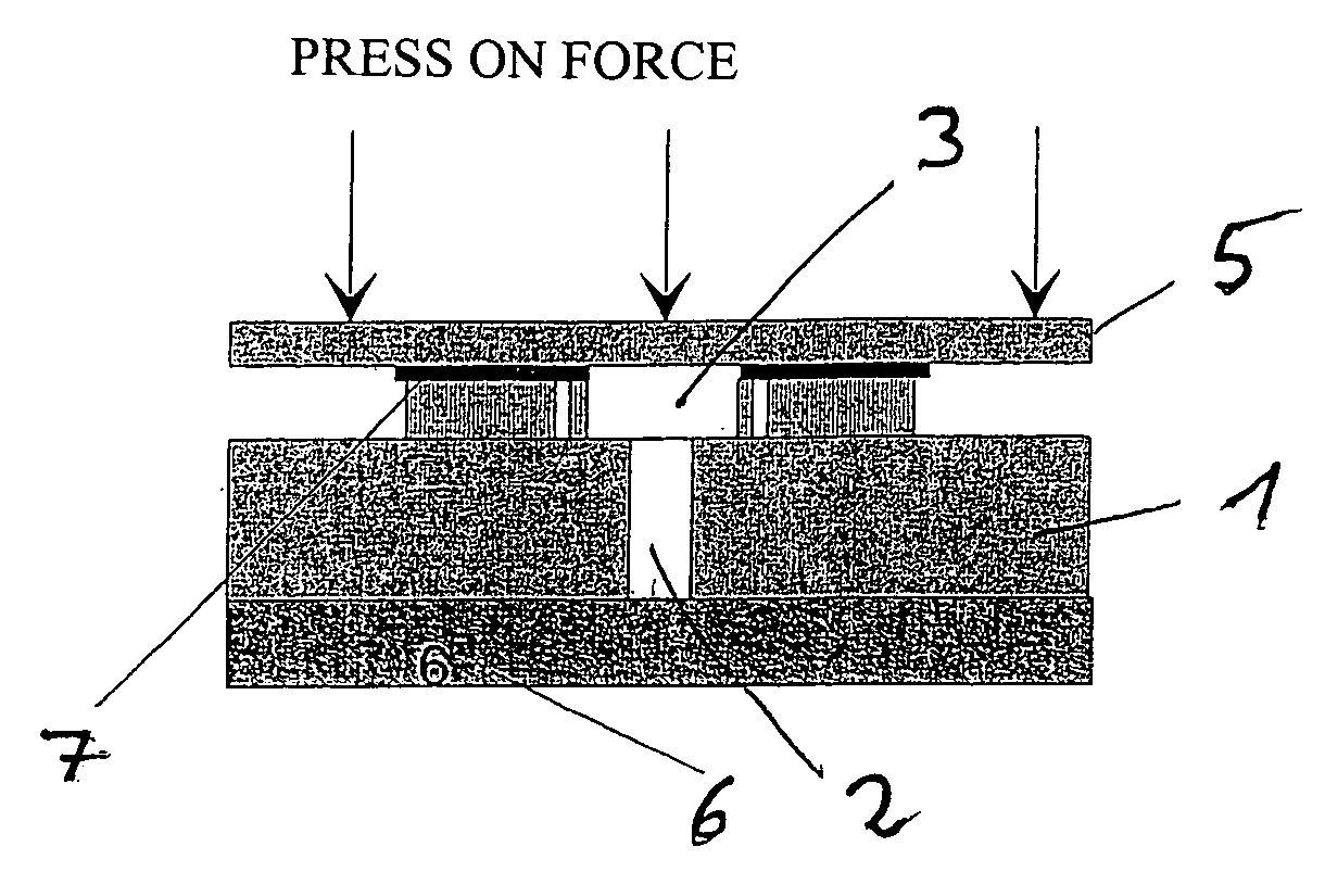
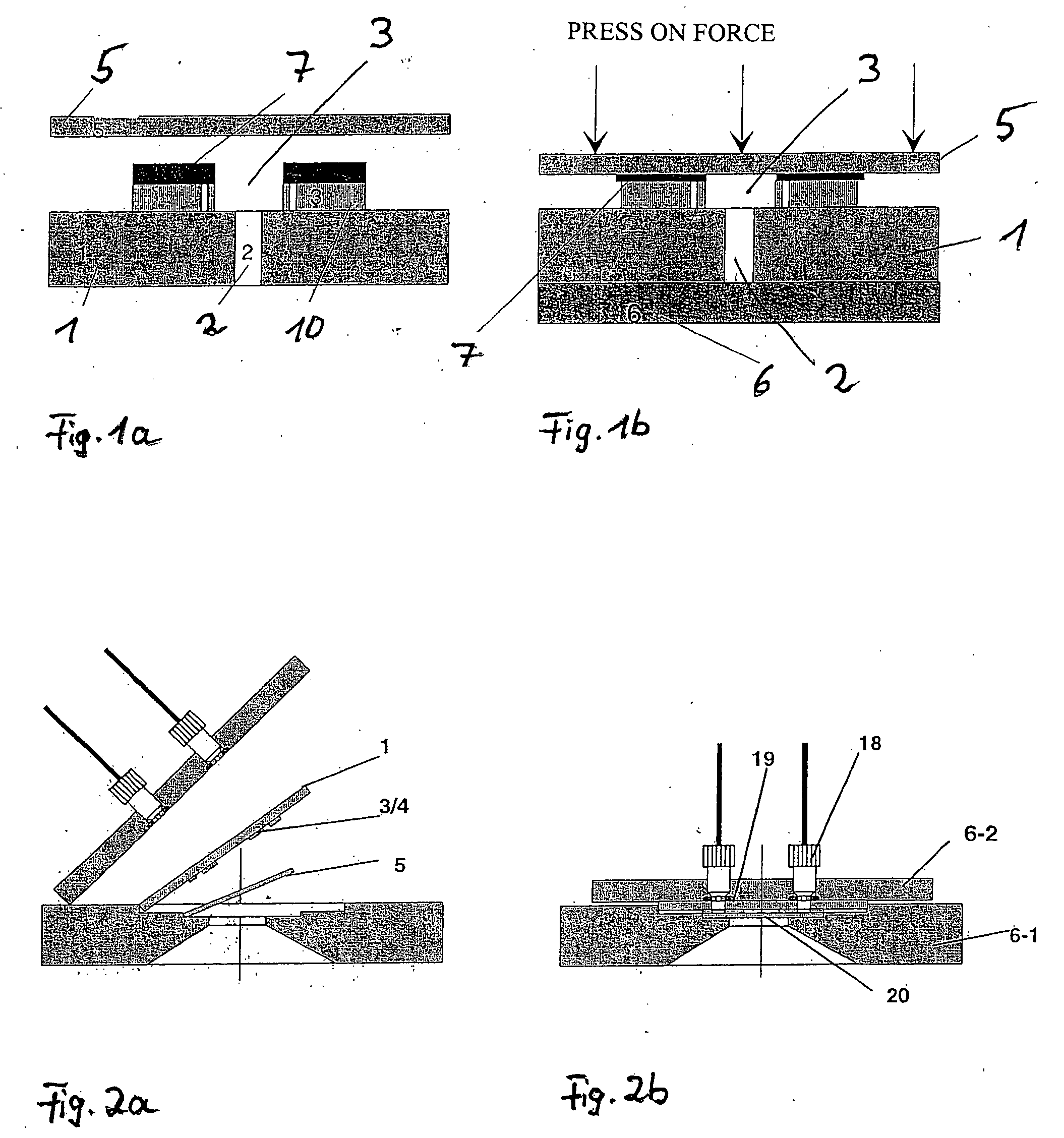
[0017] The object of the invention is to provide a method of producing 3-D microscope micro flow-through cells that are suitable for the reversible assembly of microscope flow-through cells for the .mu.l-volume range, which are open for utilization of modern microtechnologies and permit inexpensive utilization of disposable microscopy items.
[0018] The combined use of microsystem technology, such as glass drilling (e.g.: US drilling or micro sandblasting), photolithographic polymer structuring (e.g.: photosensitive resists or photoepoxy resins) and such as silk-screen printing of elastic sealing layers (e.g., silicon rubber, PDMS), permits a slide for microscopy to be functionalized so that a reversibly assemblable micro flow-through cell for the .mu.l-volume range can be produced. According to the invention, microscope flow-through cells constructed in this way are easy to remove after use, the used cover glass can be discarded and after cleaning the functionalized slide can be used over again.
[0020] The seal, which is required for fluid-tight sealing of the two substrates, is applied to the slide prior to assembly to the support in such a way that it can be used repeatedly and can easily be cleaned between the replacement processes of the cover glasses.
[0023] Applications for this device are extensive as a result of the fact that the disposable product, the cover glass, can be brought directly into engagement with the reusable product, the slide. However, a prerequisite is that the reusable product be specifically pretreated. In this way, the user may serially test as many disposable products as desired, pretreated in various ways, in a microfluidic channel system as demanding as desired.
[0048] Since inexpensive and commercially available cover glasses 5 can be used for construction of the microscope cell, minimal limits are placed on the number of flow-through cells that can be realized. The cover glasses 5 may be functionalized chemically, biologically or physically before installation, depending upon the method. When functionalization has been completed, the cover glass can be joined to the slide within seconds and without extensive adjusting work to make a closed channel system.

Problems solved by technology

The channel geometry is limited to that which is technically feasible in the structuring of the flat silicon seal, i.e., the channels are only accurate to one millimeter and can be made no thinner than 250 .mu.m.
A further drawback is that the channels can only have rough contours and cannot be fabricated with internal channel barriers, such as flow guides or flow splitters.
Further, the channels cannot be adjusted accurate to microns to structures of one or both cover glasses, and numerous applications with electrically functionalized surfaces simply cannot be performed.
The flat silicon seal is relatively costly, has a complicated chamber assembly that can easily be maladjusted in installation and is hard to keep clean.
The disadvantage of this biotechnological assembly method is that a biochemically realizable biotin / avidin contact is permanently connected.
This technology is very interesting for reusable products, but clearly too costly for disposable products.

Method used


Image

  • Method for producing a 3-D microscope flow-through cell
  • Method for producing a 3-D microscope flow-through cell
  • Method for producing a 3-D microscope flow-through cell

Examples


example

(D)

Polydimethylsiloxane (PDMS) Channel Plate

[0063] The production of a PDMS channel plate 30 is represented in FIGS. 10 and 11. FIG. 10a shows the shaping process for production of the PDMS channel plate 30 with a shaping tool (silicon-negative structure 31) before filling with PDMS and FIG. 10b the shaping tool after filling with PDMS by a PDMS inlet 32 as well as channel stoppers 33 in a PMMA plate 34. Lastly, a finished PDMS channel plate 10 is represented in FIG. 10c.

[0064] FIG. 11 shows a ready-to-use microscope cell with the PDMS channel plate.

[0065] Channel systems with the PDMS channel plate 30 meet the highest demands for accuracy, since the shaped structures are produced by microfabrication technologies in silicon and shaping of the silicon master on the PDMS silicon rubber takes place almost error-free. In order to obtain good shaping properties, the silicon master can be plasma-chemically provided with a Teflon coating.

[0066] In this case, the channel, the seal to the co...


PUM

PropertyMeasurementUnit
thickaaaaaaaaaa
thickaaaaaaaaaa
diameteraaaaaaaaaa

Abstract

The invention relates to a method of producing a 3-D microscope flow-through cell, consisting of an upper and a lower substrate between which is located a flow channel, an electrode structure penetrating the flow channel and connected with external contacts and with through-connections at the ends of the flow channel for the connection of fluid inlets and outlets. The invention provides a method of producing 3-D microscope micro flow-through cells that are suitable for the reversible assembly of microscope flow-through cells for the mum-volume range. According to the invention, this is obtained in that a base substrate is first provided with access holes and a flow channel, the flow channel being made of a sandwich of a material non-elastic inside and elastic outside, in that the flow channel for the purpose of a fluid-tight channel closure, is pressed against a second cover glass in order to provide a reversibly sealable flow channel.

Description

[0001] Then present invention relates generally to a method of producing a 3-D microscope flow-through cell, and more particularly to a flow through cell having an upper and a lower substrate between which is located a flow channel, an electrode structure penetrating the flow channel and connected with external contacts and with through-connections at the ends of the flow channel for the connection of fluid inlets and outlets.[0002] Microscope slide assemblies having a fluid flow-through cell are generally known in the art. For example, the Warner Instruments firm offers microscope chambers for the ml-volume range for micro incubation, for cell microscopy and for cell perfusion. As one of the first manufacturers of such microscope accessories, Warner Instruments has taken on the subject of reversibly assemblable micro flow-through cells. (As used herein, the term reversibly assemblable refers to a product which can be assembled. The principle of the closed microscope chamber can bes...

Claims


Application Information

Patent Timeline
Patent Type & Authority Applications(United States)
IPC IPC(8): B01L3/00G01N21/05
CPCB01L3/502707B01L3/502715B01L2200/027B01L2200/0689B01L2200/12B01L2300/0877Y10T29/49401G01N15/1484G01N21/05G01N2021/0346Y10T29/49391Y10T29/49002G01N15/1463G01N15/1433
Inventor HOWITZ, STEFFENBUERGER, MARIO
Owner GESIM GES FUR SILIZIUM MIKROSYST
Learn More