
Mail inserter

a mail inserter and envelope technology, applied in the field of mail inserters, can solve the problems of affecting the exact location of folded mail, and affecting the appearance of sealed envelopes, so as to achieve neat appearance and avoid the risk of tearing or dislocating envelopes

Inactive Publication Date: 2004-12-16
HSIEH ELTON
View PDF19 Cites 15 Cited by
  • Summary
  • Abstract
  • Description
  • Claims
  • Application Information

AI Technical Summary

Benefits of technology

[0008] It is thus a primary objective of this invention is to provide a mail inserter capable of inserting a mail to a proper location in an envelope without the risk of tearing or displacing the envelope so as to ensure a neat appearance for the sealed envelope.
[0009] It is another objective of this invention to provide a mail inserter capable of ejecting an un-flipped envelope to eliminate jamming.
[0010] It is another objective of this invention to provide a compact and lightweight mail inserter.
[0012] It is yet another objective of this invention is to provide a mail inserter that can meet the needs of print-on-demand and print-to-mail.

Problems solved by technology

Though there are several models of commercially available mail inserters that may achieve the above objectives, such conventional mail inserters use thrust to push the folded mail into an envelope such that the exact location of the folded mail cannot be properly controlled, whereby sometimes part of the folded mail is still left out of the envelope, or that the envelope may be displaced or torn by the excessive thrust upon insertion of the folded mail.
As a result, the address shown on the folded mail may not be properly displayed through the window of a windowed envelope, or the resulting sealed envelope may have a muddled appearance because the flap is not be precisely folded and sealed to the back of the envelope.
Furthermore, conventional mail inserters cannot detect whether the throat of the envelope has been properly flipped, such that jamming can easily occurred while inserting the folded mail into the un-flipped envelope
In addition, conventional mail inserters are generally large in size, which are not suitable for being used in regular office space but at a designated location, such as a mailroom.
The large size and heavy weight of conventional mail inserters prevents conventional mail inserters from being connected to a laser printer for on-line operations.
Apparently, such a process cannot meet the needs of print-on-demand and print-to-mail.

Method used


Image

  • Mail inserter
  • Mail inserter
  • Mail inserter

Examples


Embodiment Construction

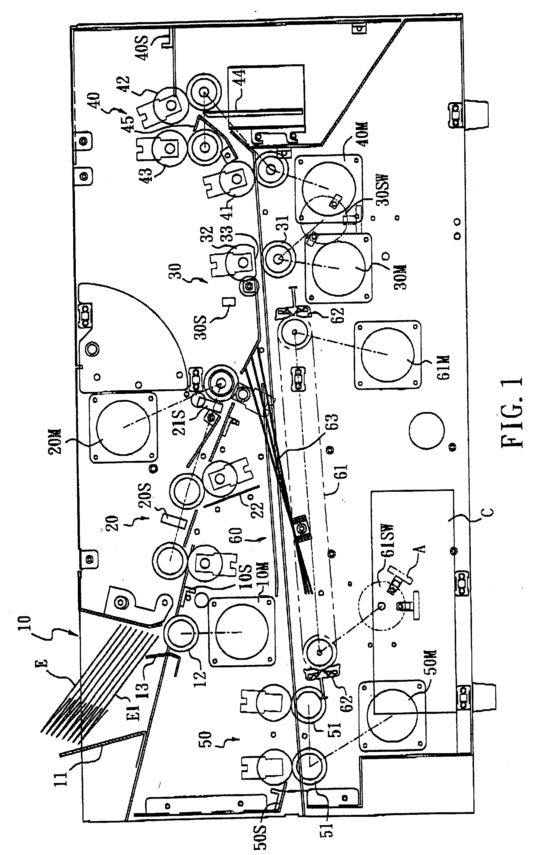
[0022] FIG. 1 illustrates a schematic, cross-sectional view of a mail inserter 1 according to this invention, illustrating the mail path and envelope path of the mail inserter 1. The mail inserter 1 according to this invention comprises: an envelope entry 10, an envelope carrier 20, an envelope retainer 30 and a sealer 40 that are sequentially provided from an upstream to a downstream to form an envelope path; and a mail entry 50 and a mail carrier 60 that are sequentially provided from an upstream to a downstream beneath the envelope path to form a mail path that merges into the envelope path between the envelope carrier 20 and the envelope retainer 30.

[0023] FIGS. 2-4 illustrates the details of the envelope entry 10, envelope carrier 20, envelope retainer 30, mail entry 50 and mail carrier 60.

[0024] As shown in FIG. 1, the envelope entry 10 includes an envelope tray 11 for holding a stack of envelopes E, an envelope entry roller 12 for advancing the bottommost envelope E1 into the...


PUM


Abstract

A mail inserter for inserting a mail into an envelope having a flap and a throat, including: an envelope entry; an envelope carrier, provided downstream of the envelope entry; an envelope retainer, provided at the downstream of the envelope carrier; a mail entry, for advancing the mail into the mail inserter; a mail carrier, provided downstream of the mail entry; a sealer, provided downstream of the envelope retainer; wherein the envelope entry, envelope carrier, envelope retainer and sealer jointly form an envelope path, and the mail entry and the mail carrier jointly form a mail path that merges into the envelope path after the mail carrier.

Description

CROSS-REFERENCES TO RELATED APPLICATIONS[0001] Not Applicable[0002] Not ApplicableDESCRIPTION[0003] This invention is related to a mail inserter, particularly to one being compact and lightweight, and allowing on-line connection with a mail collator, a folding apparatus and a printer, such as a laser printer.BACKGROUND OF INVENTION[0004] Mail inserters are commonly used for inserting a folded mail into an envelope. Though there are several models of commercially available mail inserters that may achieve the above objectives, such conventional mail inserters use thrust to push the folded mail into an envelope such that the exact location of the folded mail cannot be properly controlled, whereby sometimes part of the folded mail is still left out of the envelope, or that the envelope may be displaced or torn by the excessive thrust upon insertion of the folded mail. As a result, the address shown on the folded mail may not be properly displayed through the window of a windowed envelop...

Claims


Application Information

Patent Timeline
Patent Type & Authority Applications(United States)
IPC IPC(8): B43M3/04B43M5/04B65B5/04B65B43/26B65B43/39
CPCB43M3/045B43M5/042
Inventor HSIEH, ELTON
Owner HSIEH ELTON
Learn More