
Method and device for controlling the drive unit of a vehicle

a technology of drive unit and drive unit, applied in the field of methods and devices, can solve the problems of uncomfortable input by the driver via a conventional accelerator pedal, lost motion or dead path, and achieve the effect of increasing driving comfor

Inactive Publication Date: 2004-12-09
ROBERT BOSCH GMBH
View PDF5 Cites 0 Cited by
  • Summary
  • Abstract
  • Description
  • Claims
  • Application Information

AI Technical Summary

Benefits of technology

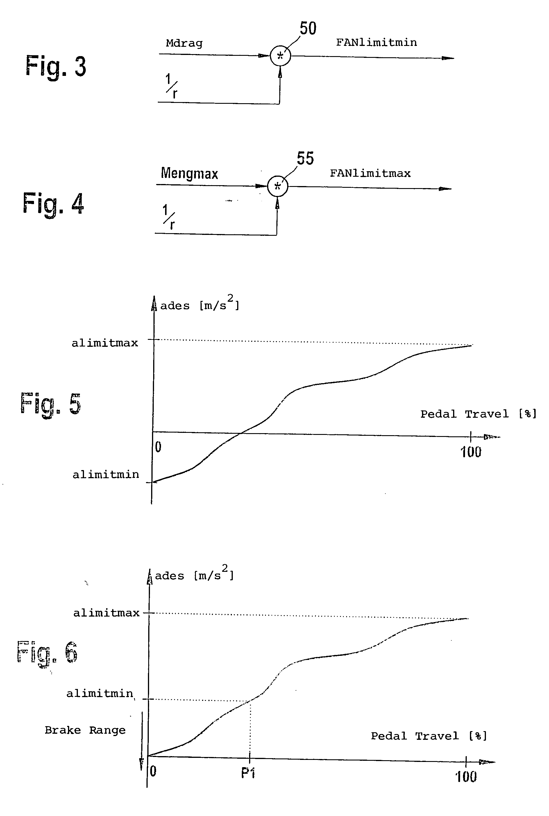
[0004] The method of the invention and the arrangement of the invention for controlling the drive unit of a vehicle with the features of the independent claims have the advantage over the above that in dependence upon an instantaneous running resistance, a minimum value and / or a maximum value for the acceleration of the vehicle is determined and that the minimum value and / or the maximum value are assigned in each case to a limit of a positioning region for the position of the operator-controlled element. In this way, the positioning region for the position of the operator-controlled element can be made current in dependence upon the instantaneous running resistance in such a manner that neither lost motion nor dead path occur when an acceleration command is inputted via the accelerator pedal. In this way, the driving comfort is increased.
[0012] A further advantage is that the allocation of the minimum value and / or of the maximum value to the particular limit of the actuating range is carried out in dependence upon an instantaneous vehicle speed. In this way, for example for downhill stretches, the additional activation of the vehicle brake with the released accelerator pedal is initiated only when a pregiven vehicle speed is exceeded in order to free the driver from a continuous actuation of the accelerator pedal to reduce a braking effect. In this way, the driving comfort is, in turn, increased.
[0005] Advantageous further embodiments and improvements of the method given in the main claim are possible via the measures set forth in the dependent claims.
[0006] It is especially advantageous when an unknown component of the running resistance is derived with the aid of a driving dynamic equation in dependence upon: an instantaneous drive force of the vehicle; a known component of the running resistance; and, an instantaneous vehicle acceleration. In this way, the instantaneous running resistance can be determined very precisely while considering a known component of the running resistance as well as while considering the unknown component thereof. This makes possible also a precise determination of the minimum value and / or of the maximum value for the acceleration of the vehicle. Lost motion and dead path can be avoided still better in this way.
[0007] It is also advantageous when the unknown component of the running resistance is filtered especially by means of a lowpass. In this way, oscillations, which result with the determination fo the unknown component, can be substantially eliminated.
[0009] A further advantage is that the maximum value of the acceleration is determined from a maximum drive force less the instantaneous running resistance with this maximum drive force being determined by the instantaneous operating point of the vehicle. In this way, the maximum value of the acceleration essentially corresponds to the vehicle acceleration reached maximally at the instantaneous operating point of the vehicle. In this way, the dead path can be avoided in the region of the upper accelerator pedal stop when the acceleration command is inputted via the accelerator pedal.
[0009] A further advantage is that the maximum value of the acceleration is determined from a maximum drive force less the instantaneous running resistance with this maximum drive force being determined by the instantaneous operating point of the vehicle. In this way, the maximum value of the acceleration essentially corresponds to the vehicle acceleration reached maximally at the instantaneous operating point of the vehicle. In this way, the dead path can be avoided in the region of the upper accelerator pedal stop when the acceleration command is inputted via the accelerator pedal.
[0010] It is especially advantageous when, in the case of a minimum value of an acceleration, which exceeds the value 0, a vehicle brake is activated at the position of the operator-controlled element assigned to the minimum value. In this way, for a released accelerator pedal and a correspondingly steep slope, for which the drag torque is no longer adequate to hold the instantaneous vehicle speed, a brake command of the driver can be detected and realized without an actuation of the brake pedal being required. In this way, the driving comfort is further increased.
[0011] It is especially advantageous when the brake force is so selected that the minimum value of the acceleration is reduced to approximately 0. In this way, the released accelerator pedal is interpreted such that the value 0 should be permitted as the smallest possible acceleration. In this way, the driving safety is especially increased in downhill stretches.
[0012] A further advantage is that the allocation of the minimum value and / or of the maximum value to the particular limit of the actuating range is carried out in dependence upon an instantaneous vehicle speed. In this way, for example for downhill stretches, the additional activation of the vehicle brake with the released accelerator pedal is initiated only when a pregiven vehicle speed is exceeded in order to free the driver from a continuous actuation of the accelerator pedal to reduce a braking effect. In this way, the driving comfort is, in turn, increased.

Problems solved by technology

The acceleration input by the driver via a conventional accelerator pedal is problematic in that the rest position of the accelerator pedal as well as the upper stop of the accelerator pedal cannot be clearly assigned to an acceleration input without a lost motion occurring, that is, a pedal travel without effect on the engine from the pedal rest position or a dead path arising, that is, a pedal travel without further action upon propulsion in the upper pedal region.
Lost motion or dead path are experienced as uncomfortable by the driver.

Method used


Image

  • Method and device for controlling the drive unit of a vehicle
  • Method and device for controlling the drive unit of a vehicle
  • Method and device for controlling the drive unit of a vehicle

Examples


Embodiment Construction

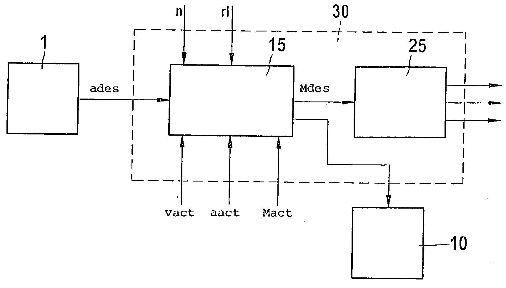
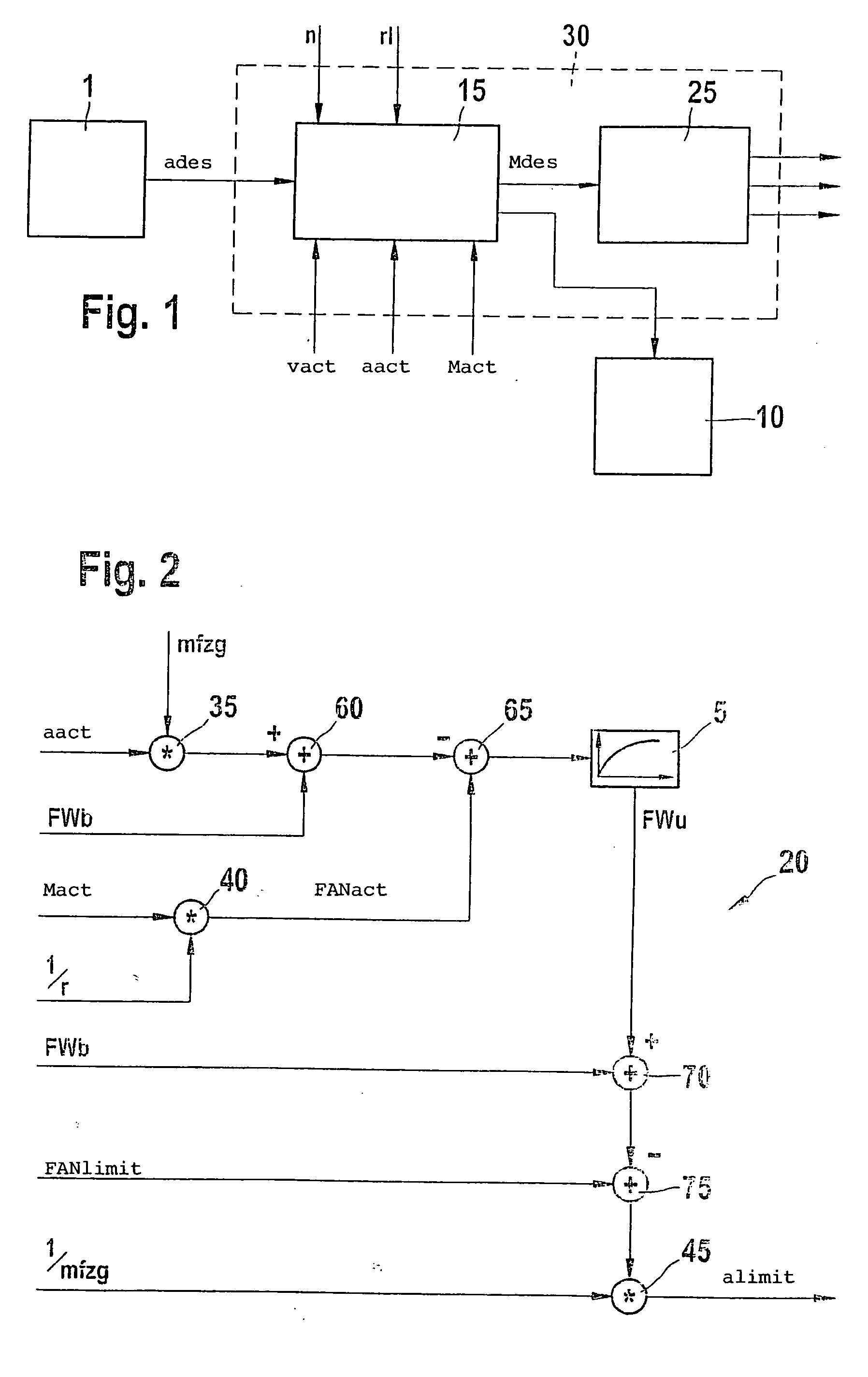
[0020] In FIG. 1, 30 identifies a motor control of a drive unit of a vehicle. The invention permits realization for any desired type of drive units. Therefore, the drive unit can, for example, include an electrodrive or an internal combustion engine. The internal combustion engine can, in turn, be, for example, a spark-ignition or a diesel engine. In the following, it will be assumed by way of example that the drive unit includes a gasoline engine. In FIG. 1, an engine control of the drive unit is identified by reference numeral 30. The engine control 30 includes means 15 for forming a desired value for an output quantity of the drive unit. The output quantity of the drive unit can, for example, be an engine output torque, a wheel torque, an engine power or the like. In the following, it will be assumed by way of example that the output quantity is a wheel torque. From detection means, which are not shown in FIG. 1 and are known to the person of skill, the following are supplied to ...


PUM


Abstract

The method involves deriving a desire for acceleration from the position of a driving pedal and forming a desired value for an output for the drive unit depending on the acceleration desire. A minimum value and a maximum value are determined depending on the instantaneous traveling resistance. The values are allocated to a limit of a setting range for setting the driving pedal. An Independent claim is also provided for an arrangement for controlling the drive unit of a vehicle.

Description

STATE OF THE ART[0001] The invention proceeds from a method and from an arrangement for controlling the drive unit of a vehicle in accordance with the class of the independent claims.[0002] The acceleration establishes itself as a central quantity for the control of the vehicle longitudinal movement in networked drive systems. Applications such as vehicle speed control or drive dynamic control utilize already an acceleration input. The acceleration input by the driver via a conventional accelerator pedal is problematic in that the rest position of the accelerator pedal as well as the upper stop of the accelerator pedal cannot be clearly assigned to an acceleration input without a lost motion occurring, that is, a pedal travel without effect on the engine from the pedal rest position or a dead path arising, that is, a pedal travel without further action upon propulsion in the upper pedal region. Lost motion or dead path are experienced as uncomfortable by the driver. The following ex...

Claims


Application Information

Patent Timeline
Patent Type & Authority Applications(United States)
IPC IPC(8): F02D11/10F02D45/00G05G1/30
CPCB60W2530/16B60W2540/10B60W2550/142B60W2720/106Y10T477/679Y10S477/905Y10T477/817Y10T74/2054F02D11/105B60W2552/15
Inventor GLORA, MICHAELMUEHLBAUER, CHRISTIANKUSTOSCH, MARIO
Owner ROBERT BOSCH GMBH
Learn More