
Method for controlling a motor vehicle operated in all-wheel drive at times

a technology of all-wheel drive and motor vehicles, which is applied in the direction of vehicle sub-unit features, transportation and packaging, and the mounting of jet propulsion devices, etc., can solve the problems of vehicle components which are involved in more than necessary stress, and the duration of coupling operations is long, so as to reduce the wear of vehicle components and increase the driving comfort

Active Publication Date: 2019-05-14
MAGNA POWERTRAIN AG & CO KG
View PDF11 Cites 1 Cited by
  • Summary
  • Abstract
  • Description
  • Claims
  • Application Information

AI Technical Summary

Benefits of technology

The invention provides a method for controlling a vehicle in all-wheel drive that allows for faster and less frequent coupling operations, resulting in improved driving comfort and reduced wear of vehicle components. This is achieved by preparing and synchronizing the torque transmission train without closing the disconnect clutch, which allows for a quicker connection of the secondary axle and also results in better driving comfort. Overall, the technical effects of the invention include faster and more comfortable driving and reduced wear on vehicle components.

Problems solved by technology

A disadvantage of known systems for coupling and decoupling a secondary axle is that coupling operations last for a long time and are sometimes carried out when this is not actually required, and therefore vehicle components which are involved are stressed more than necessary.

Method used


Image

  • Method for controlling a motor vehicle operated in all-wheel drive at times
  • Method for controlling a motor vehicle operated in all-wheel drive at times
  • Method for controlling a motor vehicle operated in all-wheel drive at times

Examples


Embodiment Construction

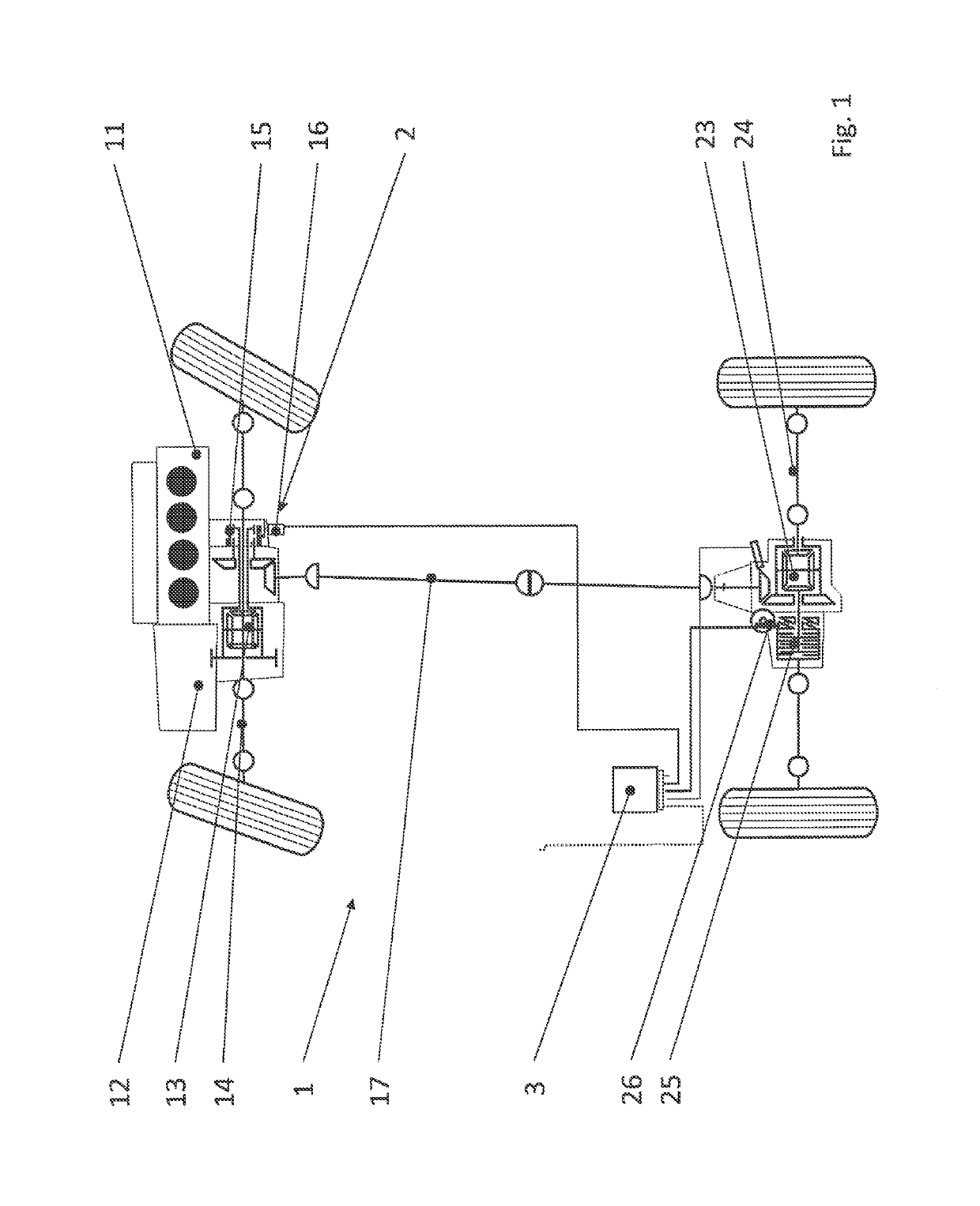
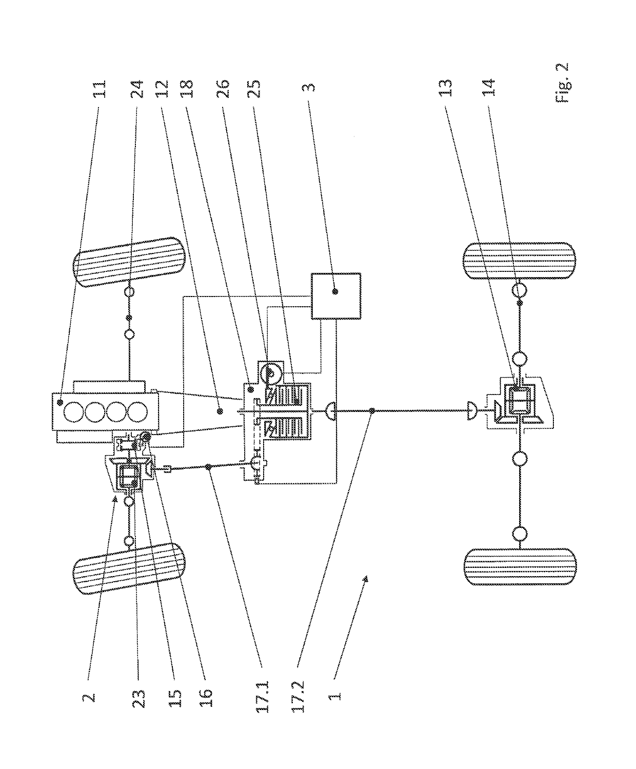
[0052]FIG. 1 illustrates a schematic view of a motor vehicle according to the invention operated in all-wheel drive at times. The motor vehicle 1 comprises in particular a drive unit 11 which is designed as an internal combustion engine, is in a transverse construction and is connected via a transmission 12 and a differential transmission 13 to a PTU 2. The PTU 2 has a disconnect clutch 15 which is actuable by a first actuating unit 16. The differential transmission 13 is connected to the primary drive axle 14, wherein the primary drive axle 14 is permanently driven. The disconnect clutch 15 is preferably designed as a dog clutch. The PTU 2 is connected to a torque transmission train 17. The torque transmission train 17 is connected to a further differential housing 23. The differential housing 23 has a second clutch device 25, designed as a hang-on clutch, which is connectable to the secondary drive axle 24. The actuation of the hang-on clutch 25 takes place by means of a second ac...


PUM


Abstract

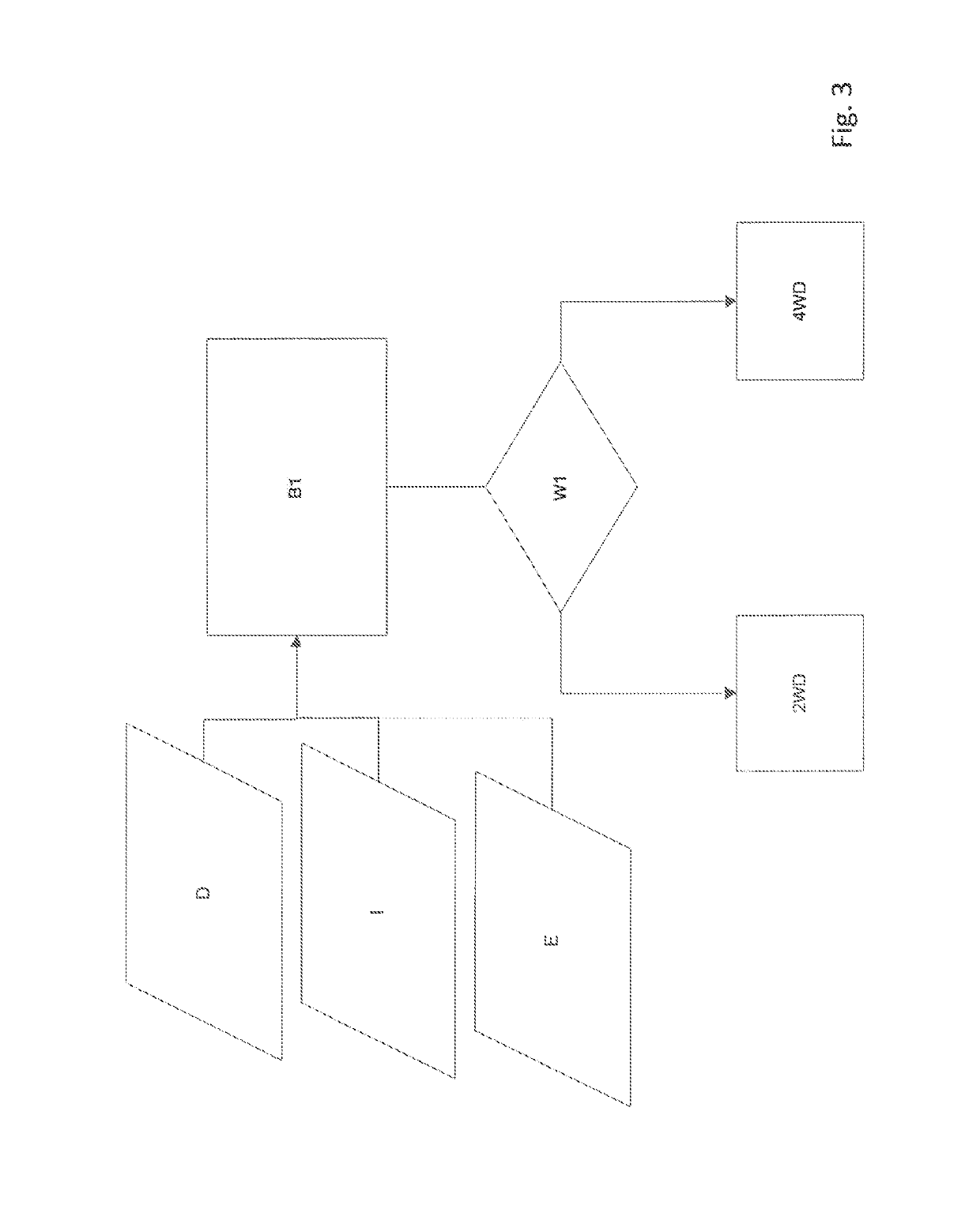
A method for controlling a motor vehicle (1) operated in all-wheel drive at times, by means of a control unit (3), wherein the motor vehicle comprises a drive unit (11), a primary drive axle (14) permanently driven by the drive unit (11), a secondary drive axle (24), a torque transmission train (17, 17.1) for transmitting the torque of the drive unit (11) to the secondary drive axle (24), and a disconnect clutch (15) for coupling the secondary drive axle (24) to and uncoupling same from the drive unit (11), wherein the control unit (3) can actuate the disconnect clutch (15) via a first actuating unit (16), characterized by the following stepsdetermining an all-wheel requirement for the motor vehicle from input signalsif there is a predetermined all-wheel requirement, preparing an all-wheel operation, wherein the disconnect clutch (15) is not closed.

Description

CROSS-REFERENCE TO RELATED APPLICATION[0001]This application is a National Stage of International Application No. PCT / EP2014 / 056752 filed Apr. 3, 2014 and which claims the benefit and priority of German Patent Application No. DE 102013206242.7 filed Apr. 9, 2013, the entire disclosures of which are incorporated herein in their entirety by reference.FIELD OF THE INVENTION[0002]The invention relates to a method for controlling a motor vehicle operated in all-wheel drive at times, by means of a control unit. For this purpose, the motor vehicle comprises a drive unit, a primary drive axle permanently driven by the drive unit, a secondary drive axle, a torque transmission train for transmitting the torque of the drive unit to the secondary drive axle, and a disconnect clutch for coupling the secondary drive axle to and decoupling same from the drive unit. The control unit can actuate the disconnect clutch via a first actuating unit.PRIOR ART[0003]A method for axle disconnect is known fro...

Claims


Application Information

Patent Timeline
Patent Type & Authority Patents(United States)
IPC IPC(8): B60K5/02B60K17/35B60K23/08B60K5/04B60K17/346B60K17/344
CPCB60K23/08B60K17/35B60K5/02B60K5/04B60Y2400/421B60K17/3462B60K2023/0858B60Y2300/73B60K17/344
Inventor QUEHENBERGER, JOHANNES
Owner MAGNA POWERTRAIN AG & CO KG
Learn More