
Interface transceiver power mangagement method and apparatus

a power mangagement and interface technology, applied in the field of communication link circuits, can solve the problems of increasing the operating frequency and complexity of the interface between present-day system devices and also between circuits, jitter reduction, phase correction, error correction, error recovery circuit and equalization circuit that can become very complex, and relatively complex receivers and high-power transmitters

Inactive Publication Date: 2004-10-14
IBM CORP
View PDF30 Cites 28 Cited by
  • Summary
  • Abstract
  • Description
  • Claims
  • Application Information

AI Technical Summary

Problems solved by technology

Interfaces between present-day system devices and also between circuits have increased in operating frequency and complexity.
In particular, high speed serial interfaces require data / clock extraction, jitter reduction, phase correction, error correction, error recovery circuits and equalization circuits that can become very complex, depending on the performance requirements of a particular interface.
Due to limited design resources and the need to satisfy the requirements of multiple interface applications, customers and channel conditions, transmitters and receivers within above-described interfaces are typically designed for the worst-case bit error rates and environmental conditions, leading to relatively complex receivers and high power transmitters.
As a result, it is not always possible to provide a receiver that is not more complex than necessary when a high channel quality is available.
The complexity of the above-mentioned receivers increases as the worst-case error rates and interface conditions deviate from the ideal.
Complexity of the transmitter may also increase due to the use of digital equalization circuits and error correction encoding.

Method used


Image

  • Interface transceiver power mangagement method and apparatus
  • Interface transceiver power mangagement method and apparatus
  • Interface transceiver power mangagement method and apparatus

Examples


Embodiment Construction

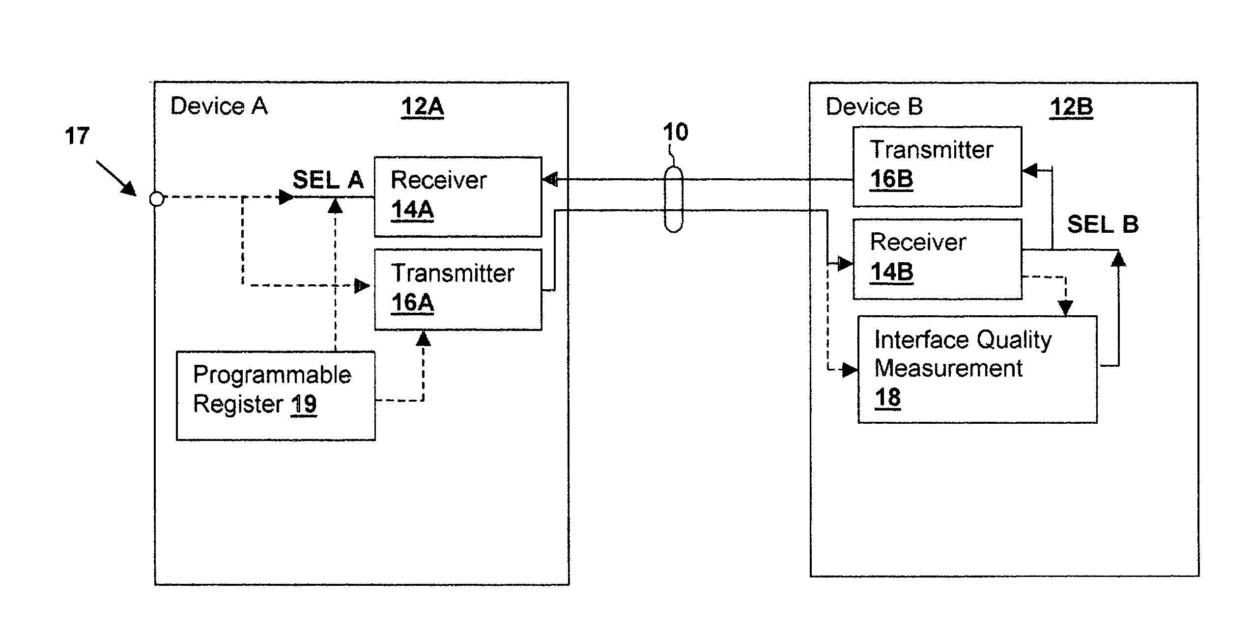
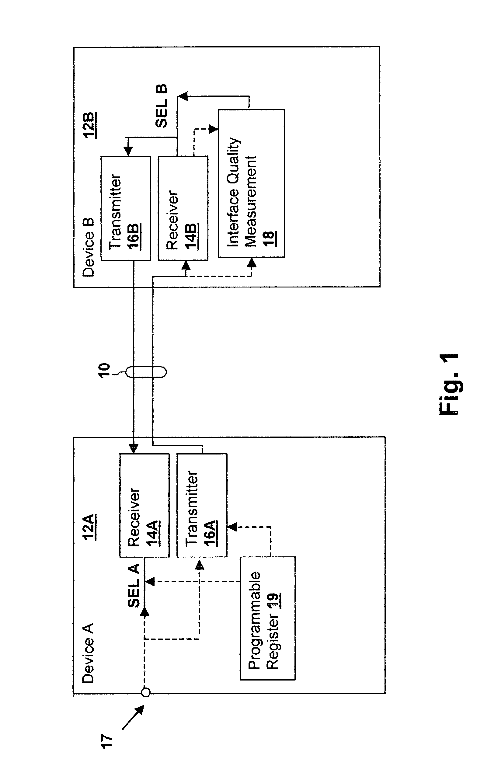
[0017] With reference now to the figures, and in particular with reference to FIG. 1, there is depicted a block diagram of transceivers 12A and 12B connected by an interface or channel 10 in accordance with an embodiment of the invention. Transceivers 12A, 12B may be located within a device such as a computer peripheral, a computer system, or within integrated circuits interconnected within a system. Interface 10 may be a single two wire bi-directional interface as depicted, or may be a full-duplex single wire interface or a bus having multiple transceivers in a half-duplex or full-duplex configuration. Transceivers 12A and 12B connected to interface 10 each using a receiver 14A and 14B and a transmitter 16A and 16B, but the present invention is applicable to receivers and / or transmitters and it should be understood that a receiver or transmitter in accordance with an embodiment of the invention may be incorporated in devices for connection to any of the above-specified types of int...


PUM


Abstract

An interlace transceiver power management method and apparatus reduces power consumption when interface conditions will support a transceiver having reduced complexity. Characteristics of the receiver and / or transmitter are adjusted in conformity with one or more selection signals. An interface quality measurement circuit may provide the selection signal, so that the transceiver complexity is adjusted in response to measured interface conditions or an external pin or register bit may be coupled to a select input. The receiver complexity adjustment may include the receiver sampling depth, window width, resolution or equalization complexity or other characteristic having an impact on receiver circuit power consumption. The transmitter complexity may be equalization, transmitter power or other characteristic having an impact on transmitter circuit power consumption. The select signal may be communicated from one transceiver to another, so that the power consumption at a remote location is determined by local measurement or programming.

Description

[0001] 1. Technical Field[0002] The present invention relates generally to communication link circuits, and more particularly, to transmitters and / or receivers having selectable complexity and power consumption.[0003] 2. Description of the Related Art[0004] Interfaces between present-day system devices and also between circuits have increased in operating frequency and complexity. In particular, high speed serial interfaces require data / clock extraction, jitter reduction, phase correction, error correction, error recovery circuits and equalization circuits that can become very complex, depending on the performance requirements of a particular interface. As the above-mentioned circuits become more complex, they have an increasingly large proportion of digital logic and the overall amount of digital logic employed in both receiver and transmitter circuits has increased substantially.[0005] Due to limited design resources and the need to satisfy the requirements of multiple interface a...

Claims


Application Information

Patent Timeline
Patent Type & Authority Applications(United States)
IPC IPC(8): H04B1/16
CPCH04B1/16H04B1/40H04B17/00
Inventor CARBALLO, JUAN-ANTONIOBOERSTLER, DAVID WILLIAMBURNS, JEFFREY L.
Owner IBM CORP
Learn More