
Method for producing airbags

a technology of airbags and airbags, applied in the direction of pedestrian/occupant safety arrangements, electromagnetic radiation sensing, instruments, etc., can solve the problems of not being reliably "seen" by automatic sensing systems, unable to adapt an action to the discrete contour of the airbag in the fabric, and deviations in the fabric, especially as regards the dimensions of the opw, which cannot be automatically taken into account or corrected

Inactive Publication Date: 2004-10-14
GLOBAL SAFETY TEXTILES
View PDF9 Cites 10 Cited by
  • Summary
  • Abstract
  • Description
  • Claims
  • Application Information

AI Technical Summary

Benefits of technology

[0010] This method has the major advantage that the incorporated markers now ensure that the resulting fiducials in the fabric are machine-readable and always reliably attained in the subsequent steps in the process. This method permitting any desired position and number of markers now makes it possible to correct any deviations in contour and dimensions in and between the discrete air bags located in the woven web on patterning and in addition to reliably place fiducials in subsequent steps in the process, now irrespective of the fact that a textile is live and each variation of the air bag makes for different requirements.

Problems solved by technology

Air bag fabrics currently employed, especially for OPW air bags, including air bags woven multi-ply contoured make it very difficult to adapt an action to the discrete contour of the air bag in the fabric.
The woven single-ply contour hardly stands out, for example, from woven two-ply portions, resulting in it failing to be reliably "seen" by automatic sensing systems.
This means that any deviations in the fabric, especially as regards dimensions of the OPW fail to be automatically taken into account or corrections make manually intervention in the program sequence necessary.
This, as a rule, involves halting the machine with serious disadvantages in time and money in making the correction and possibly resulting in a high percentage of rejects in continuation of the program (possibly incorrect).
In the online gaging systems as used in the aforementioned patterning systems, implementing gaging on unblanked OPWs in the air bag fabric at defined locations lacks reliability because the woven contours cannot be reliably sensed.
Establishing the values necessitates manual gaging at considerable cost and manual expenditure.

Method used


Image

  • Method for producing airbags

Examples


Embodiment Construction

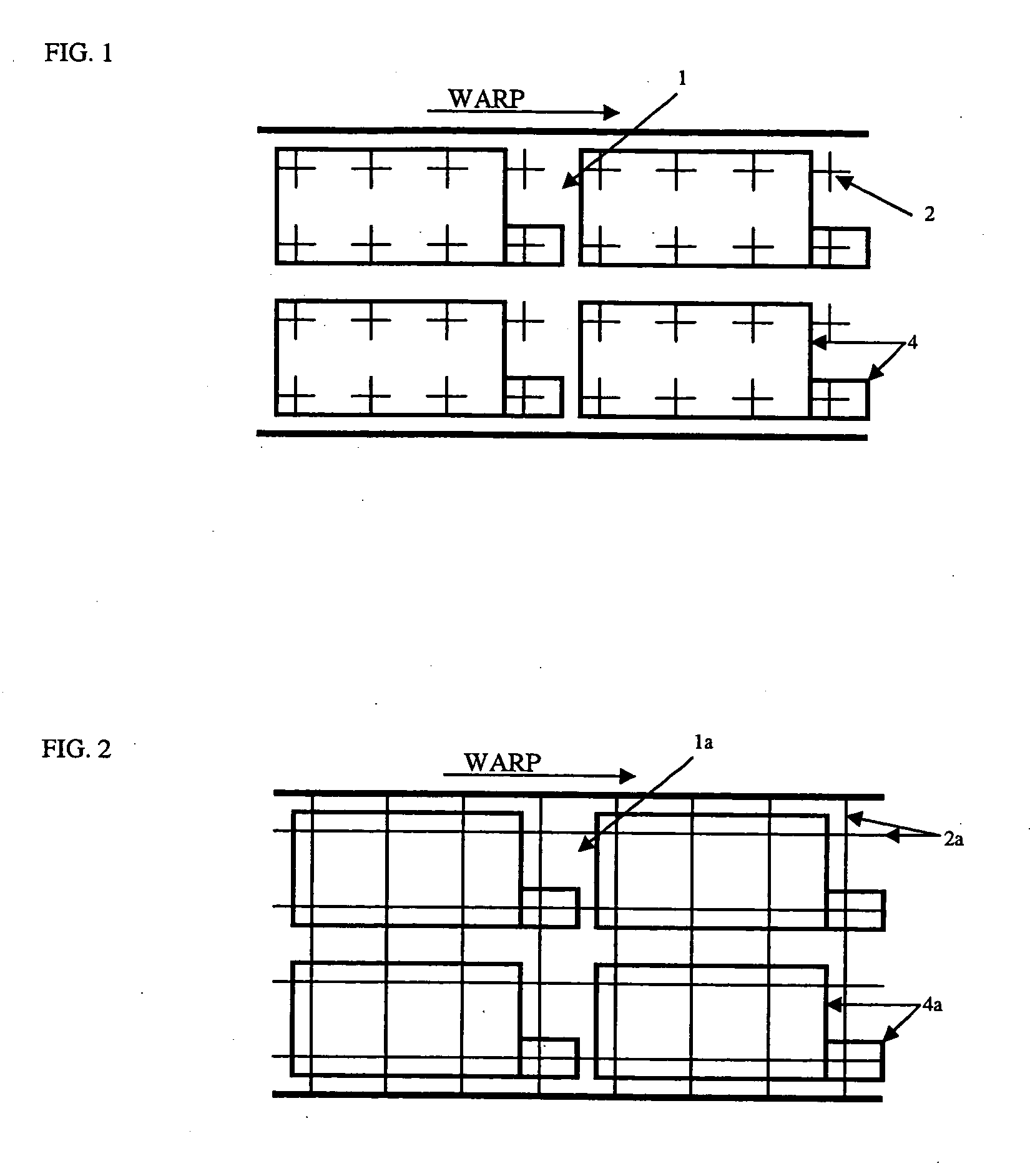
[0012] The invention will now be described by way of an example in producing an OPW. In preparing the warp threads in the warping shop, warp threads suitable as machine-readable marker threads are already included in the warp. In weaving the air bag fabric weft threads suitable as machine readable marker threads are included in the weave of at least part of the cloth width. In subsequent cutting out the air bag from the air bag fabric by means of a cutting system, the cutter is guided by said machine-readable marker threads included in the weave.

[0013] Before or during cutting the actual positions of these threads or markers are "seen" in a suitable system and compared to the wanted positions stored in a program sequence for cutting OPW or air bag parts and the differences used in automatically adapting the cutting program (e.g. re-sizing). This now eliminates costly manual intervention, automatic adaption permitting production to extremely tight tolerances as well as extremely crit...


PUM

PropertyMeasurementUnit
widthaaaaaaaaaa
sizeaaaaaaaaaa
dimensionsaaaaaaaaaa

Abstract

The invention relates to a method for producing woven airbags, especially at least partially multi-layered airbags. Said method comprises the following steps: a) the warp threads are prepared in the warping room, warp threads which are suitable as marker threads for machine-readable markings being already placed in the warp; b) the airbag material is woven, weft threads which are suitable as marker threads for machine-readable markings being interlaced over at least part of the width of the cloth; and c) the airbag is cut out of the airbag material using a cutting device which is guided by the interlaced machine-readable markings.

Description

BACKGROUND AND SUMMARY OF THE INVENTION[0001] The present invention relates to a method for producing woven air bags, particularly multi-ply at least in part, as well as to a fabric, particularly for air bags multi-ply in part.[0002] After weaving, fabrics, especially for partly multi-ply air bags, are as a rule cut to size on patterning tables. Air bags configured multi-ply in part as woven in once piece on weaving machines are termed "one-piece-woven" (OPW) air bags. The ply and contour of the OPW air bag in the web of fabric coming from the weaving machine are intended as specifications for a cutting system.[0003] Air bag fabrics currently employed, especially for OPW air bags, including air bags woven multi-ply contoured make it very difficult to adapt an action to the discrete contour of the air bag in the fabric. Although for the sake of simplicity the term OPW is used throughout the following description, it is understood that this includes air bag fabrics, woven air bags and...

Claims


Application Information

Patent Timeline
Patent Type & Authority Applications(United States)
IPC IPC(8): D06H1/04B26D5/00B26F1/38B60R21/16D03D1/02D03D11/00D03D15/00D06H1/00D06H7/00
CPCB26D5/005B26F1/3806D03D1/02D03D11/00D03D15/00D06H1/00D10B2401/16D10B2505/124Y10T83/0605Y10T83/2087
Inventor BUSSKAMP, HEINZBECKER, MICHAELESCHBACH, THOMASHUBER, NORBERT
Owner GLOBAL SAFETY TEXTILES
Learn More