Tire building arrangement and method

Inactive Publication Date: 2004-08-19
CONTINENTAL AG
View PDF6 Cites 1 Cited by
  • Summary
  • Abstract
  • Description
  • Claims
  • Application Information

AI Technical Summary

Benefits of technology

[0011] The device or arrangement of the invention includes two main axes wherein a second axis is arranged between a center line of a carcass building drum and a center line of a shaping drum. The device is a simpler and more compact structure compared with the prior art and can be created in a surprisingly simple manner. Since the belt building drum, according to the invention, is arranged nearer to the carcass building drum, an operation of the device by one person is rendered possible. As noted above, this can be accomplished without the machine output being reduced compared with conventional devices that are usually operated by two people. The invention also provides that one person or operator can control the application processes on the carcass building drum as well as the application processes on the belt building drum.

Problems solved by technology

Such devices for building vehicle pneumatic tires have the disadvantage that they are structured with a very large surface area and are very extensive.
In such a device the carcass building drum and the belt building drum lie so far apart that the operation of the device (i.e., the control of the application processes) by one person is only possible with reduced machine output.
These distances are simply too far for one person to cover.
Moreover, the use of one person to operate in such a device renders the tire building process too time-consuming and inefficient.
The disadvantage with this device for building vehicle pneumatic tires is that the device, as a whole, is structured with a very large surface area, i.e., it takes up a very large amount of area, and functions in a very complicated manner due to the arrangement of three machine axes.

Method used


Image

  • Tire building arrangement and method
  • Tire building arrangement and method

Examples


Embodiment Construction

[0045] The particulars shown herein are by way of example and for purposes of illustrative discussion of the embodiments of the present invention only and are presented in the cause of providing what is believed to be the most useful and readily understood description of the principles and conceptual aspects of the present invention. In this regard, no attempt is made to show structural details of the present invention in more detail than is necessary for the fundamental understanding of the present invention, the description taken with the drawings making apparent to those skilled in the art how the several forms of the present invention may be embodied in practice.

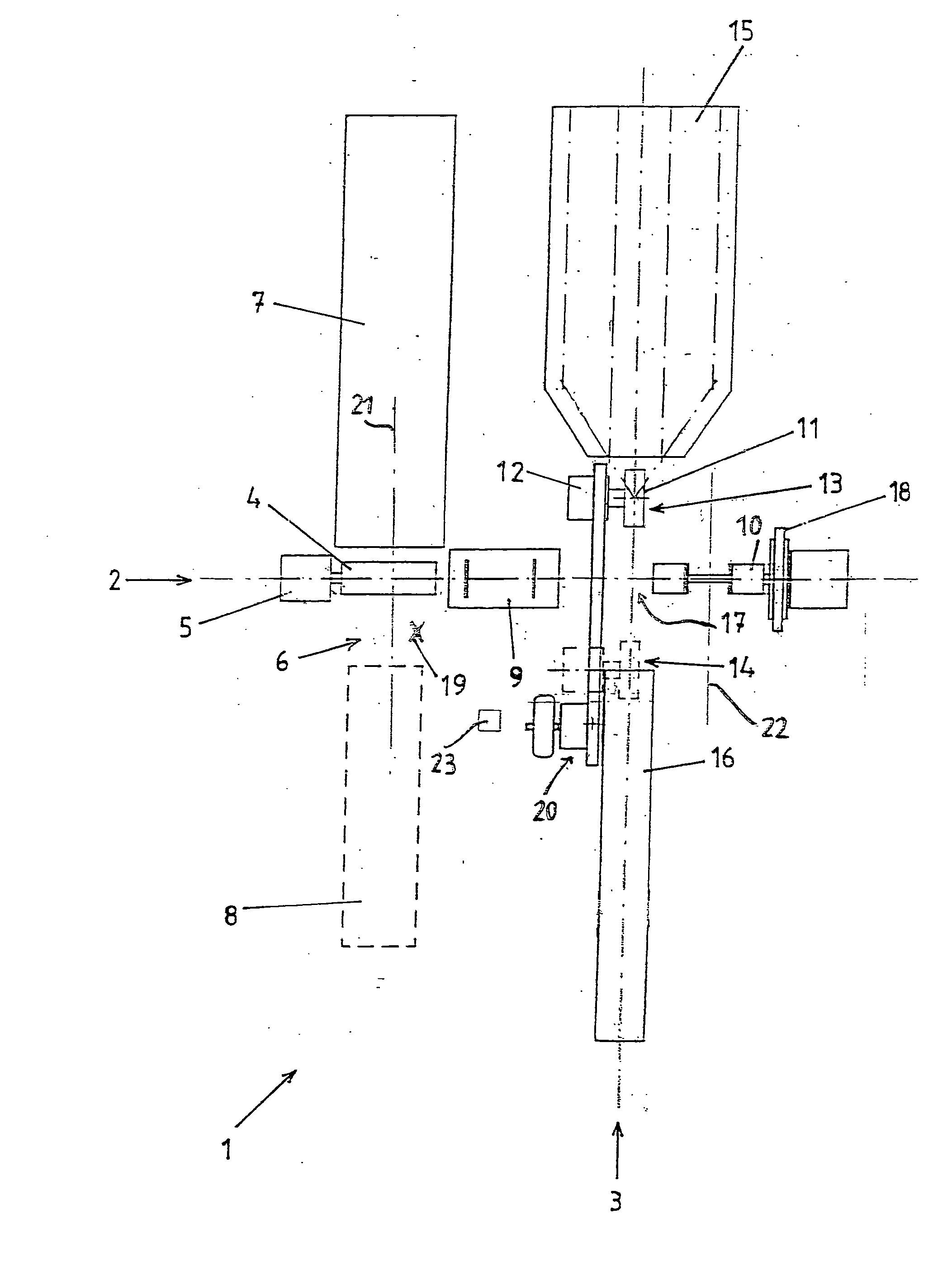
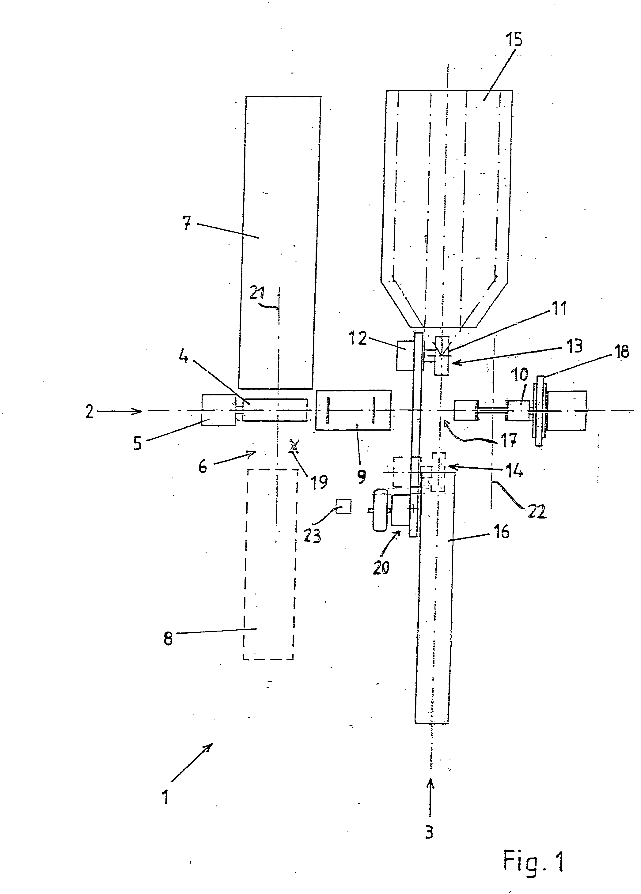
[0046] FIG. 1 shows a general view of the tire building device, arrangement or system 1 in plan view. The arrangement 1 includes devices for two production lines. A first production line is arranged along a first axis 2 and a second production line is arranged along a second axis 3. These axes 2, 3 are arranged at an ang...


PUM

PropertyMeasurementUnit
Angleaaaaaaaaaa
Angleaaaaaaaaaa
Angleaaaaaaaaaa

Abstract

Arrangement and method of building vehicle pneumatic tires. The arrangement has a first production line including a carcass building drum device, a shaping drum device, and a moveable core-centering and carcass-carrying device arranged between the carcass building drum device and the shaping drum device. The moveable core-centering and carcass-carrying device is adapted to receive a carcass from the carcass building drum device and to transfer the carcass the shaping drum device. A second production line includes a movable belt building drum device adapted to build a belt package with at least one belt layer. The movable belt building drum device is adapted to move across the first production line and between the carcass building drum device and the shaping drum device. This Abstract is not intended to define the invention disclosed in the specification, nor intended to limit the scope of the invention in any way.

Description

[0001] The present application claims priority under 35 U.S.C. .sctn.119 of German Patent Application No. 103 05 895.8, filed on Feb. 13, 2003, the disclosure of which is expressly incorporated by reference herein in its entirety.[0002] 1. Field of the Invention[0003] The invention relates to an arrangement and method for building vehicle pneumatic tires.[0004] 2. Discussion of Background Information[0005] Known devices for building vehicle pneumatic tires comprise a carcass building drum for building a carcass, a moveable core-centering and carcass-carrying device to receive the prefabricated carcass from the carcass building drum and to transfer the prefabricated carcass provided beforehand with bead cores to a shaping drum, a belt building device with a belt building drum for building the belt package with one or more belt layers, and a shaping drum for joining the prefabricated carcass to the belt package.[0006] The classic production of a new tire by means of such a device is d...

Claims


Application Information

Patent Timeline
IPC IPC(8): B29D30/20
CPCB29D30/20
Inventor RINGHOFF, HUBERTJORDINE, WILFRIEDJUNGK, ANDREAS
Owner CONTINENTAL AG
Why Eureka
Try Eureka