
Method and system for diagnostic approach for fault isolation at device level on peripheral component interconnect (PCI) bus

a technology of peripheral components and fault isolation, applied in the field of hardware fault diagnosis and system, can solve problems such as no approach, master or slave can generate errors, and system shutdown

Inactive Publication Date: 2004-06-17
IBM CORP
View PDF2 Cites 8 Cited by
  • Summary
  • Abstract
  • Description
  • Claims
  • Application Information

AI Technical Summary

Benefits of technology

[0012] Another purpose is to provide a method and structure which does not require history tables or a pattern history table, thereby resulting in decreased hardware requirements.
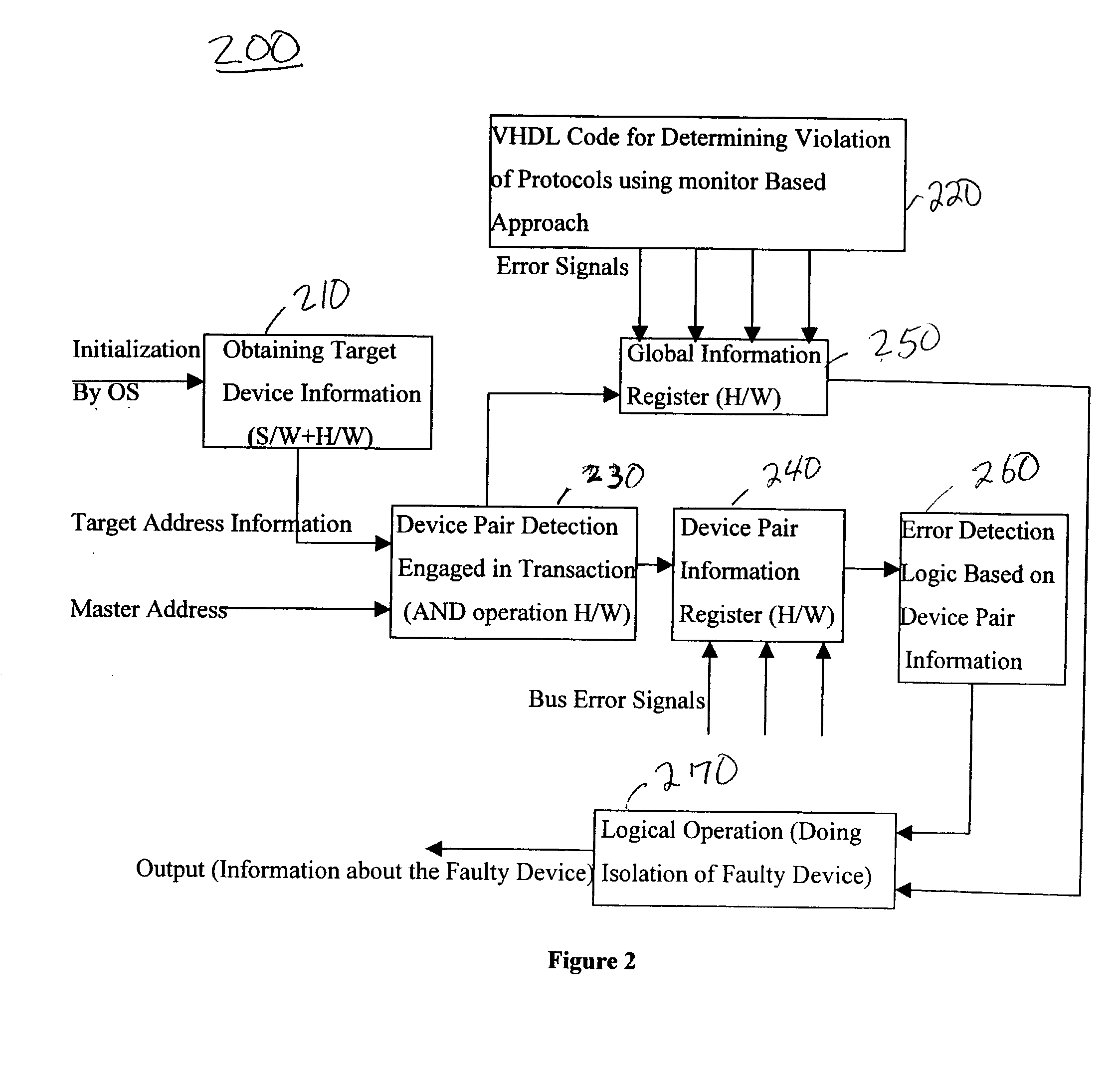
[0015] With the unique and unobvious features of the present invention, the culprit device can be pinpointed using Boolean logic based on alloyed prediction rather than weights based on misprediction. Additionally, this approach does not require history tables (such as a pattern history table), thereby resulting in reduced hardware. Additionally, the invention allows the OS to take any necessary actions based on the seriousness of the error.
[0018] That is, the system must return to an idle state, which will help to find deadlock states. Additionally, the termination type should not change during a single transaction which helps in checking if an agent can signal a target abort in one cycle and then return a retry in the next clock cycle before the transaction ends.

Problems solved by technology

In PCI architecture, either a master or a slave can generate errors.
Some of these errors are serious in nature, such as a parity error which may result in the generation of serious interrupts like a nonmaskable interrupt (NMI), further resulting in a shut-down of the system.
This creates the need to pinpoint the device which is causing the problems during the transaction phase.
However, prior to the present invention, there was no approach, which could pinpoint a culprit device using Boolean logic based on alloyed prediction, rather than weights based on misprediction.
Instead, conventional approaches required history tables or a pattern history table, thereby resulting in increased hardware and system complexity.
Additionally, this approach does not require history tables (such as a pattern history table), thereby resulting in reduced hardware.

Method used


Image

  • Method and system for diagnostic approach for fault isolation at device level on peripheral component interconnect (PCI) bus
  • Method and system for diagnostic approach for fault isolation at device level on peripheral component interconnect (PCI) bus
  • Method and system for diagnostic approach for fault isolation at device level on peripheral component interconnect (PCI) bus

Examples


embodiment

PREFERRED EMBODIMENT

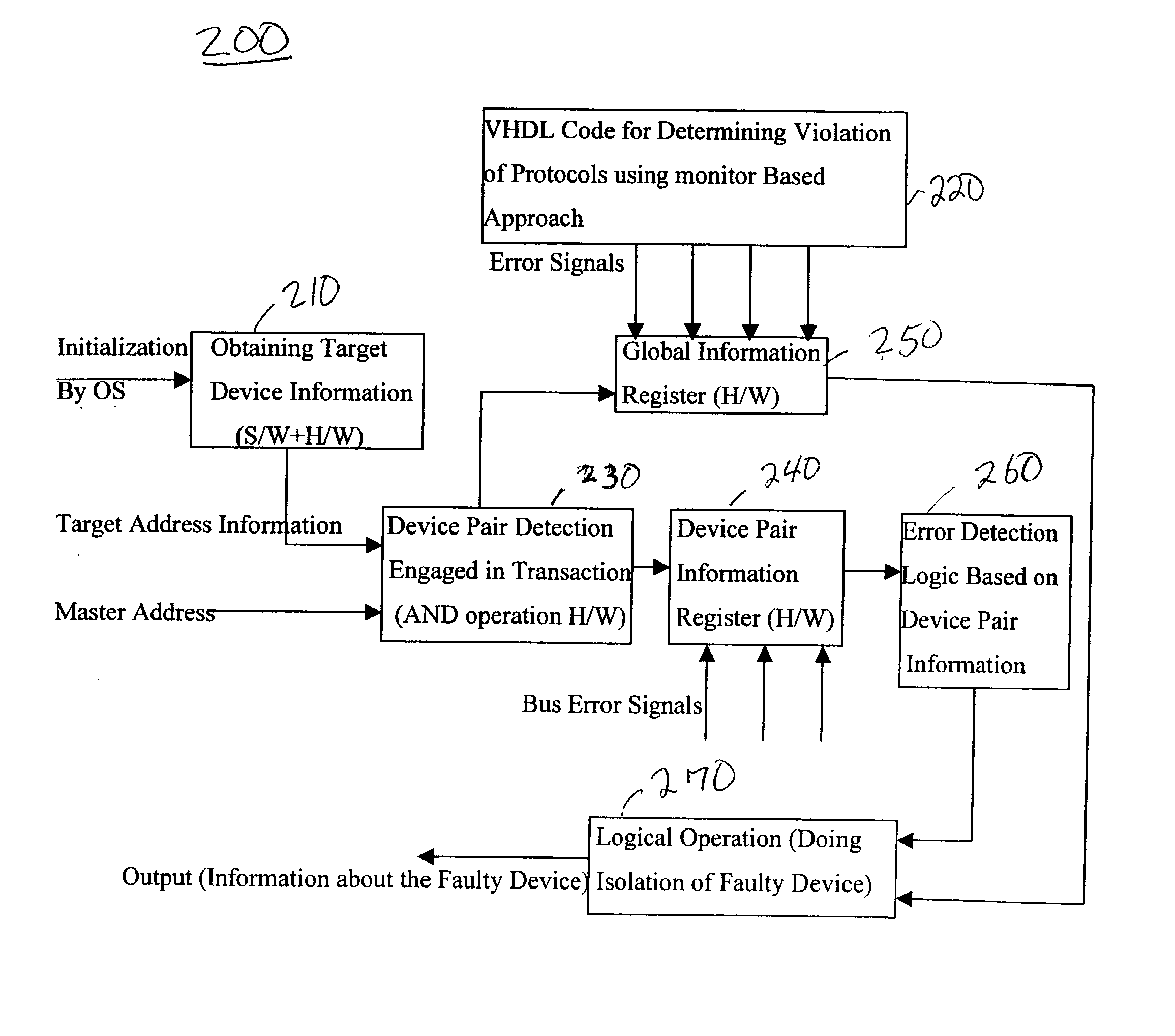
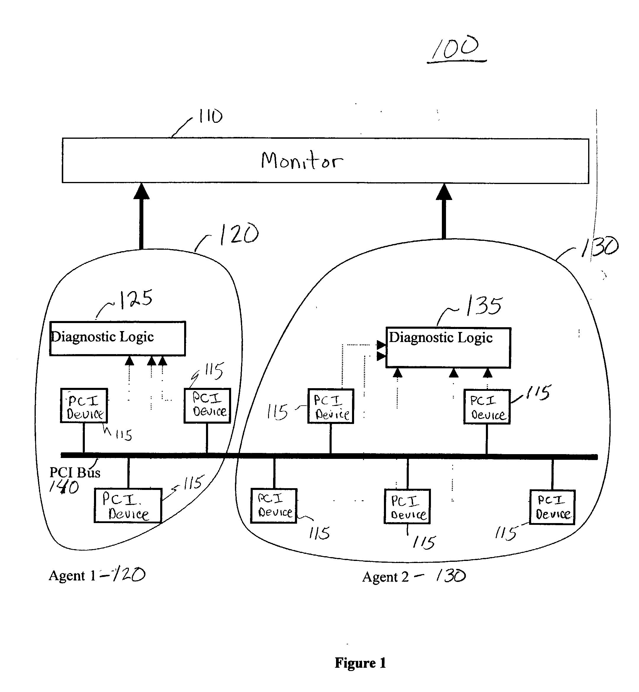
[0039] FIG. 1 shows a high level architecture 100 of the approach and environment of the present invention, including a monitor 110 and a plurality of agents (e.g., first and second agents) 120, 130 which are linked together via a PCI bus 140. Each of the agents may include one or more PCI devices 115. The two monitor agents 120, 130 have been created to be responsible for checking the PCI constraints to be followed by the devices under their supervision.

[0040] A diagnostic logic 125, 135 is present in each environment (e.g., agent 120, 130) and will govern the faulty device in its mode of operation or any other problem related to the bus.

[0041] The dashed lines (unreferenced) in FIG. 1 are for GNT signals, DEVSEL signals, bus error signals, PCI Bus protocol signals and the like between the PCI device(s) 115 and the diagnostic logic 125, 135.

[0042] Thus, the two monitor agents 120, 130 have been created which will be responsible for checking the PCI constraints t...


PUM


Abstract

A method (and system) monitoring a bus with pair-wise participants, includes detecting a problem during a transaction between first and second participants on the bus, and determining which participant is at fault for the problem or whether the problem includes a systemic bus problem.

Description

[0001] 1. Field of the Invention[0002] The present invention generally relates to a method and system for diagnosing a fault in hardware, and more particularly to a method and system for diagnosing a fault in a device on a peripheral component interconnect (PCI) bus.[0003] 2. Description of the Related Art[0004] Hardware prediction techniques are used for predicting the operation of the hardware. A hardware predictor can be implemented as a finite state machine that outputs a prediction of an unknown value of particular bit(s) given some input bits and its internal state.[0005] The logic used for prediction typically works in two modes. A first mode is called a "prediction mode" (e.g., it accepts an input and produces an output) and the second mode is called an "update mode" (e.g., it accepts an input and updates its past record).[0006] Since mispredictions waste power and cycles, it is desirable to avoid them. To minimize this problem, Alloyed Predictors have been developed. They r...

Claims


Application Information

Patent Timeline
Patent Type & Authority Applications(United States)
IPC IPC(8): G06F11/26G06F13/00H04B1/74
CPCG06F11/079G06F11/0745
Inventor HARPER, RICHARD EDWINSINGH, TARUN DEEP
Owner IBM CORP
Learn More