
Auto setting for network devices

a network device and auto setting technology, applied in the field of auto setting for network devices, can solve the problems of extreme load of setting operations, time-consuming and labor-intensive setting operations for network devices,

Inactive Publication Date: 2004-05-20
SEIKO EPSON CORP
View PDF5 Cites 36 Cited by
  • Summary
  • Abstract
  • Description
  • Claims
  • Application Information

AI Technical Summary

Benefits of technology

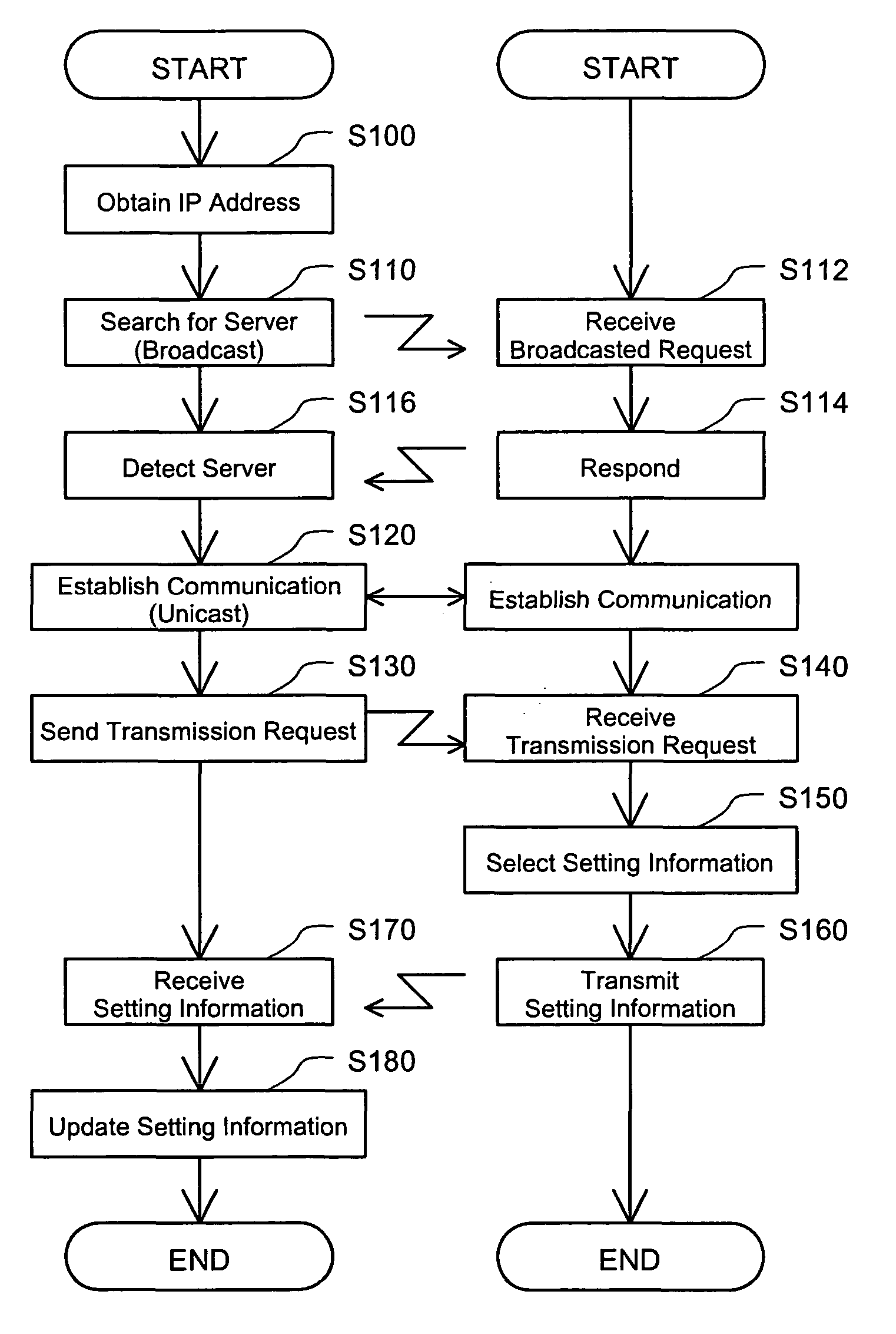
[0009] The network device obtains the setting information from the information processing device to implement auto setting. This arrangement desirably relieves the load of setting operations for initial setting or setting update of the setting information in the network device. The setting information sent from the information processing device to the network device may be only the setting information mapped to the predetermined identification information allocated to the network device or may otherwise include setting information mapped to identification information allocated to another network device.
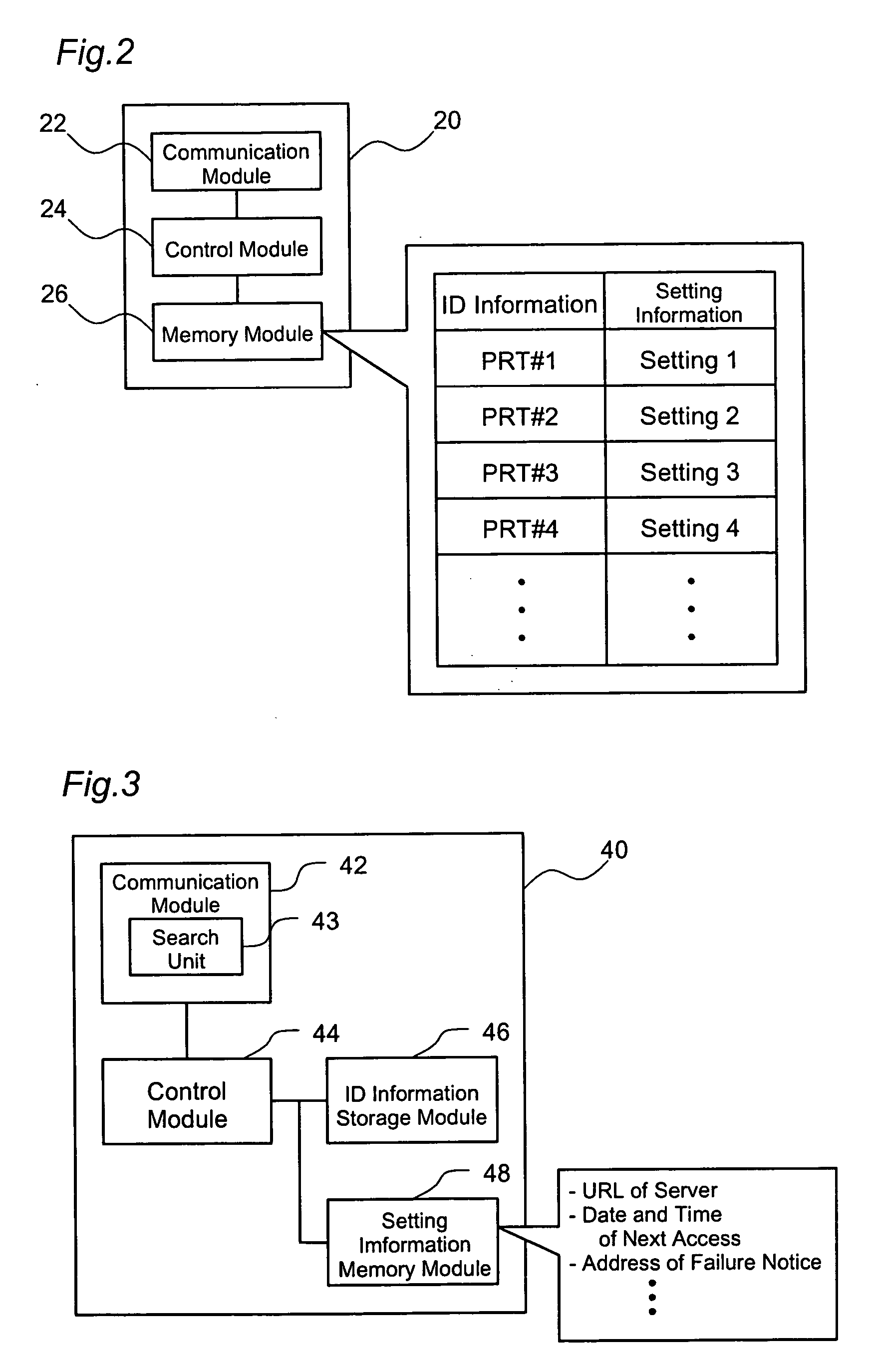
[0011] When the network device collectively receives multiple series of setting information mapped to identification information of multiple network devices from the information processing device, this arrangement enables the network device to select only a series of setting information mapped to the predetermined identification information allocated to the network device among the multiple series of setting information and adequately update the stored setting information with the selected series of setting information.
[0013] This structure causes the information processing device to transmit the setting information in response to the transmission request sent from the network device. Even when a firewall is present between the network device and the information processing device, the network device can readily obtain the setting information through an access to the information processing device.
[0017] This structure enables the network device to send the transmission request to the information processing device at a timing specified by the information processing device, for example, at a timing of update of the setting information stored in the information processing device, in order to obtain and update the setting information. The arrangement desirably reduces non-required accesses to the information processing device.
[0031] The identification information set after shipment of the network device is, for example, an IP address or a `name` of the network device. This arrangement enables the user to flexibly set the identification information in the network device.
[0033] Available examples of the identification information set based on the location of the network device include global positioning information of the network device by the GPS (Global Positioning System), coordinate information of the network device in a preset space, and floor or area information on or in which the network device is located, like the first floor or the second floor of a building. The global positioning information may be input automatically from a GPS cell phone or another position detector into the network device or may be input manually by the user. When the network device at a certain location is replaced by another network device, the setting information for the old network device can readily be carried over to the replaced network device.

Problems solved by technology

The setting operations for the network devices are rather time-consuming and labor-consuming.
Especially when it is required to perform settings in a large number of network devices, as in the case where a company installs a lot of network devices all at once, there is an extreme load of the setting operations.

Method used


Image

  • Auto setting for network devices
  • Auto setting for network devices
  • Auto setting for network devices

Examples


modified example 2

F2. Modified Example 2

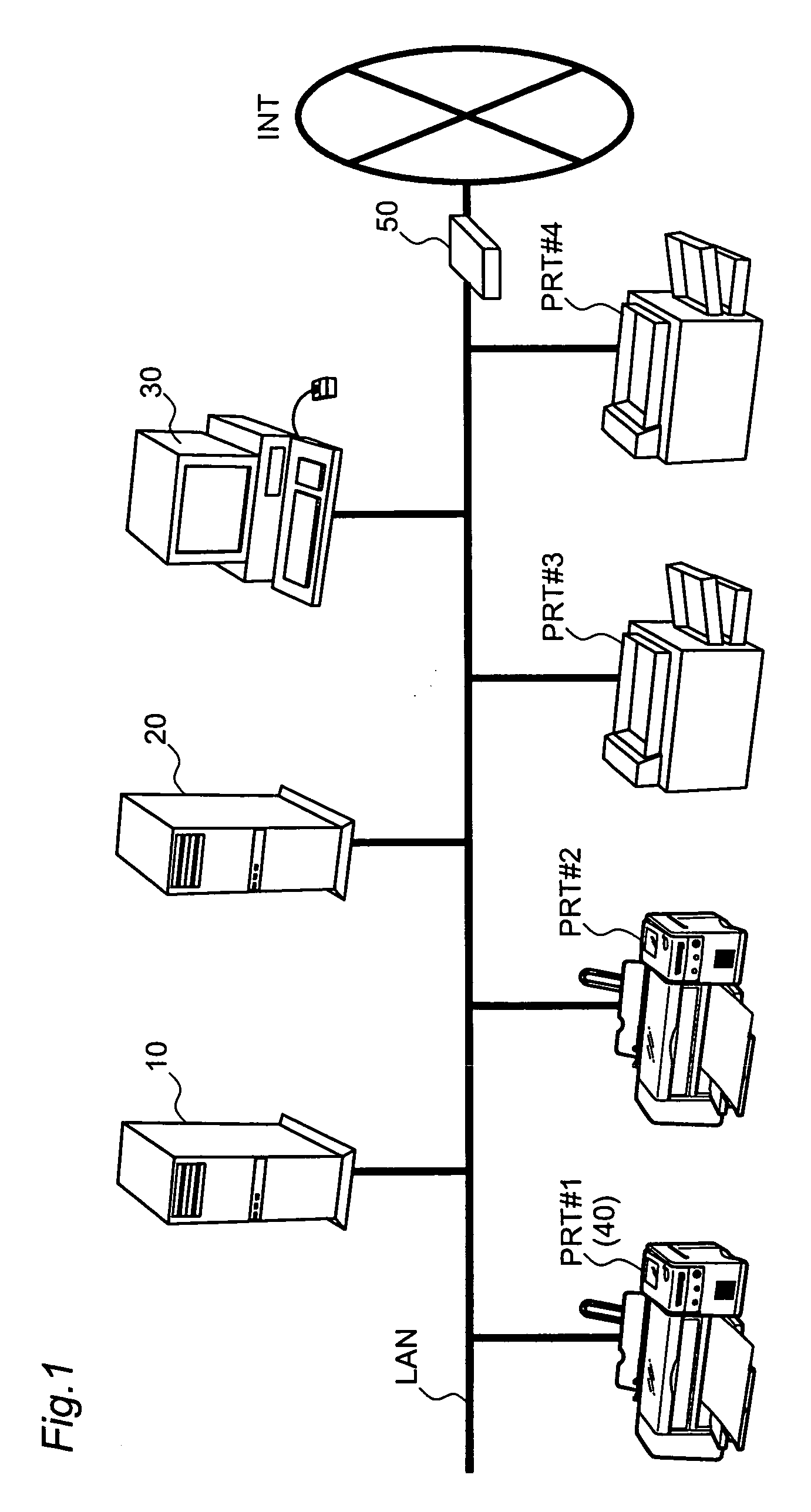
[0086] In either of the above embodiments, the server 20 is located on the LAN, to which the printers 40 are connected. The server 20 may, however, be located on another network. When the server 20 is located on another network, however, the router 50 limits the external access to the LAN. It is accordingly preferable that each of the printers 40 pulls the setting information out of the server 20, instead of the push-type transmission of the setting information from the server 20 to the printer 40.

modified example 3

F3. Modified Example 3

[0087] In the structure of the first embodiment, the printer 40 has the search unit 43, which searches for the location of the server 20 on the LAN. In one modified structure, the server 20 may have a search unit that searches for the location of each printer 40 on the LAN.

modified example 4

F4. Modified Example 4

[0088] In the structure of the second embodiment, in response to every update of the setting information stored in the memory module 26, the server 20 transmits all pieces of the setting information to each of the printers 40 by multicast, regardless of the presence or the absence of the setting information transmission request from the printer 40. This arrangement is, however, not restrictive at all. In one possible modification, the server 20 transmits a notice showing that the setting information has been updated to each of the printers 40 by unicast, and the printer 40 receives the notice and sends a setting information transmission request to the server 20 to obtain the setting information.


PUM


Abstract

A server is connected with multiple printers as network devices via a network. The server maps setting information to MAC addresses of the respective printers and stores the mapping to consolidate the management. Each of the printers sends a setting information transmission request including its own MAC address to the server. The server then selects setting information mapped to the MAC address and transmits the selected setting information to the printer. The printer receives the transmitted setting information and updates the storage contents of a built-in setting information memory module, based on the received setting information. This arrangement effectively relieves the load of setting operations for various network devices.

Description

[0001] 1. Field of the Invention[0002] The present invention relates to auto setting for network devices.[0003] 2. Description of the Related Art[0004] Various network devices, such as personal computers, network printers, and routers, have been used in various fields. Such network devices require diverse settings to establish connection with a network and utilize services, for example, trouble reporting to a network administrator.[0005] The setting operations for the network devices are rather time-consuming and labor-consuming. Especially when it is required to perform settings in a large number of network devices, as in the case where a company installs a lot of network devices all at once, there is an extreme load of the setting operations.[0006] The object of the present invention is thus to remove the drawback of the prior art technique and to relieve the load of setting operations for a network device.[0007] In order to attain at least part of the above and the other related ...

Claims


Application Information

Patent Timeline
IPC IPC(8): G06F3/12B41J29/38G06F13/00H04L12/24H04L12/28H04L29/12
CPCH04L12/24H04L29/12009H04L29/12047H04L61/15H04L41/0803H04L41/0856H04L41/00H04L61/45H04L61/00
Inventor SHIMA, TOSHIHIRO
Owner SEIKO EPSON CORP
Learn More