
Vertically downward type back-light module

a backlight module and vertical downward technology, applied in the direction of lighting and heating apparatus, instruments, mechanical equipment, etc., can solve the problems of increasing the surface area of the reflective element, affecting the uniformity of light, and affecting the fabrication cos

Inactive Publication Date: 2004-04-22
KUO HENG HUANG
View PDF5 Cites 41 Cited by
  • Summary
  • Abstract
  • Description
  • Claims
  • Application Information

AI Technical Summary

Benefits of technology

[0009] It is another object of the invention to provide a vertically downward back-light module that is dimensionally reduced to an adequate thinness.

Problems solved by technology

Due to the constraints of electron beam technology, this traditional display device usually requires the mount of a voluminous electron tube.
The light uniformity therefore is not satisfactory.
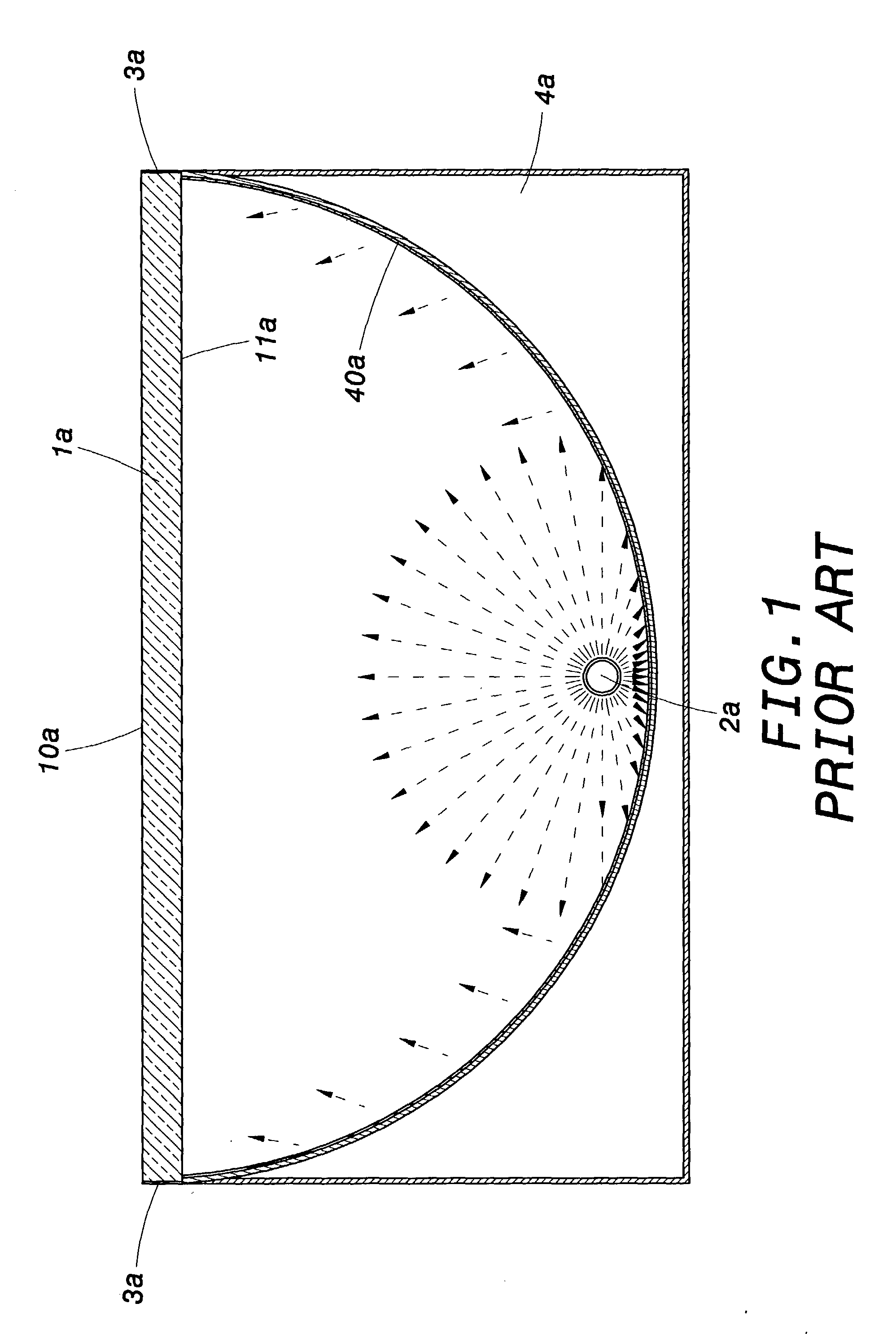
Furthermore, due to the arcuate shape of the base, the size and more particularly the thickness of the back-light module are therefore relatively large, which increases the surface area of the reflective element and, consequently, the fabrication cost.

Method used


Image

  • Vertically downward type back-light module
  • Vertically downward type back-light module
  • Vertically downward type back-light module

Examples


Embodiment Construction

[0019] Wherever possible in the following description, like reference numerals will refer to like elements and parts unless otherwise illustrated.

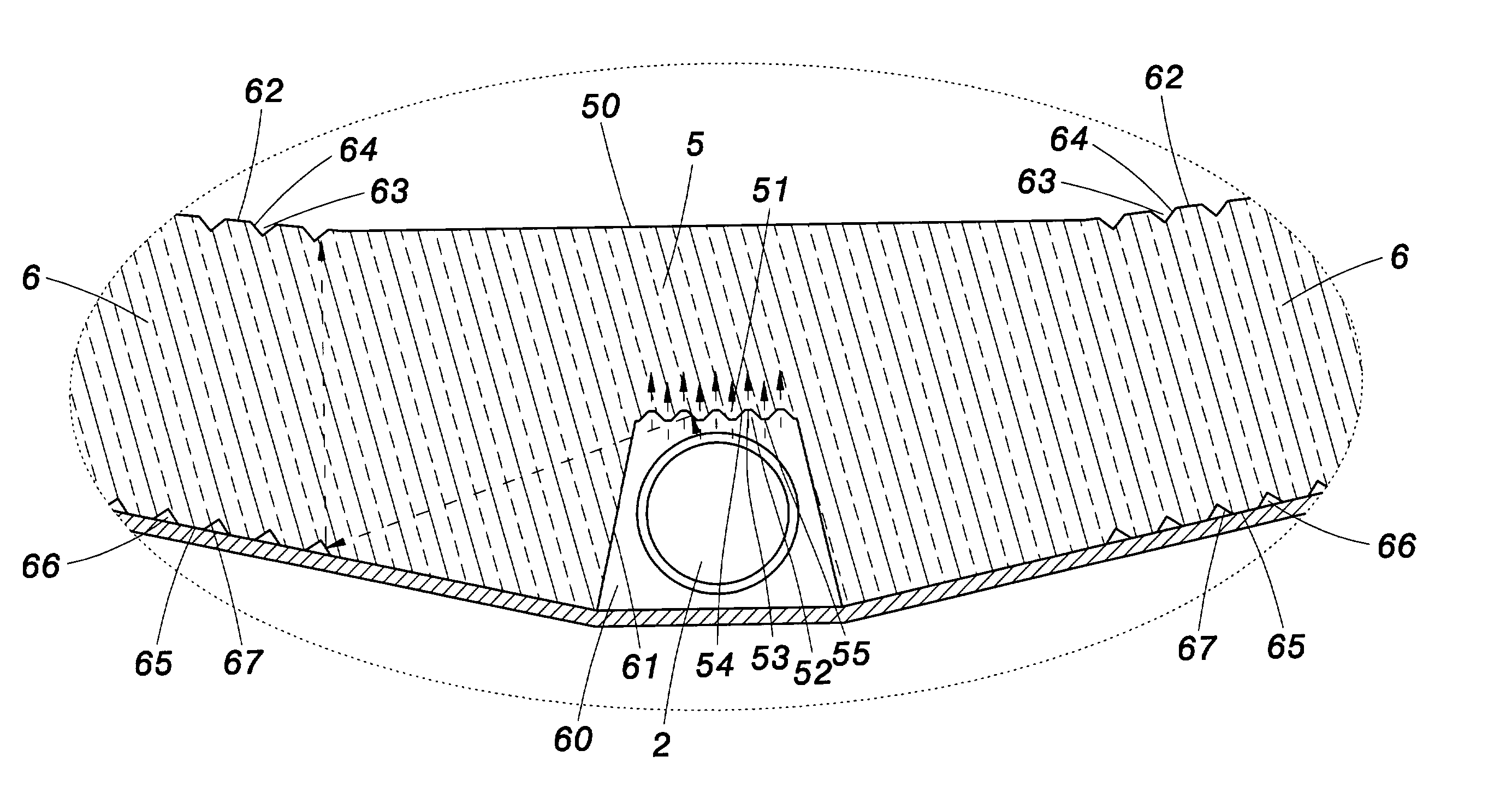
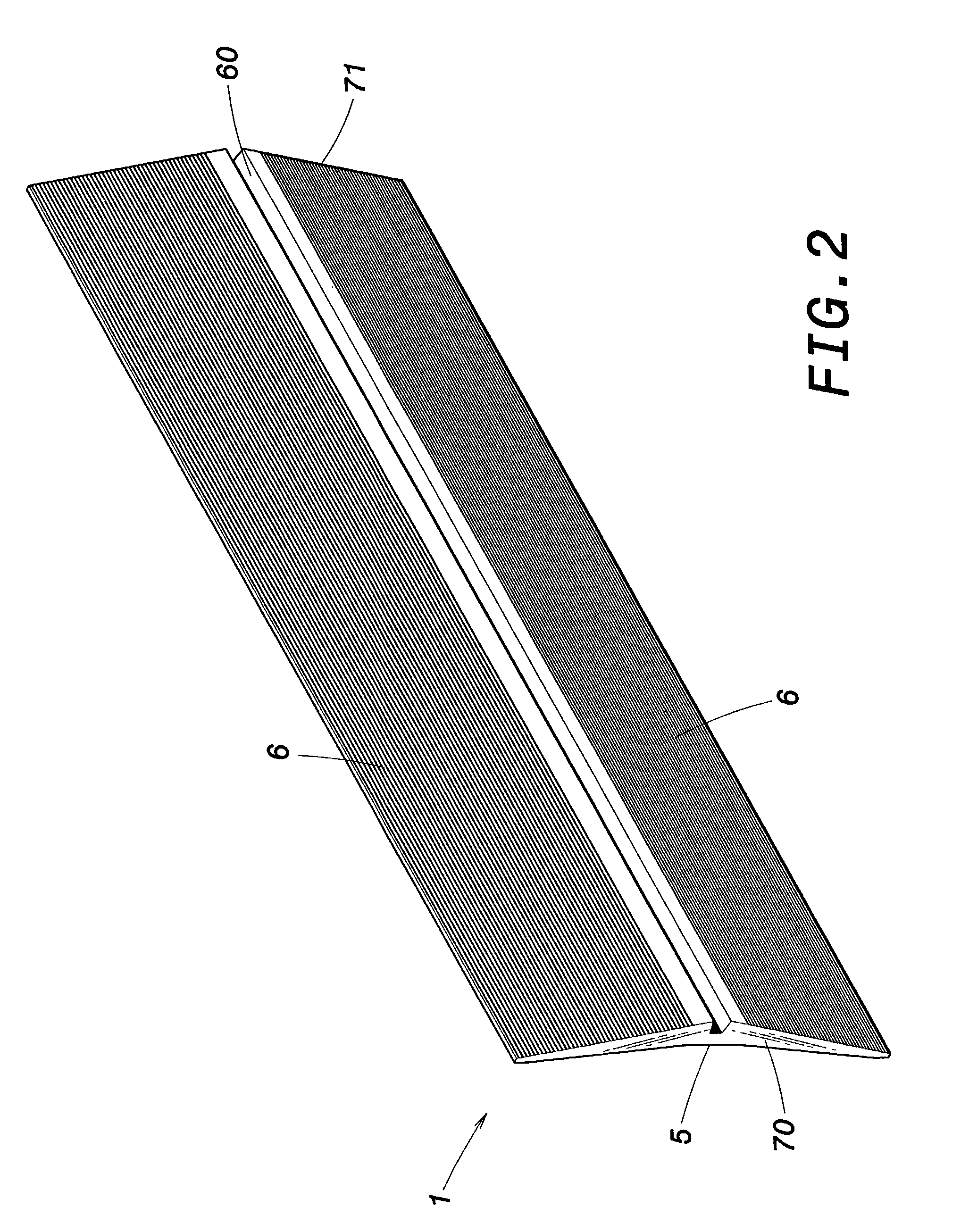
[0020] Reference now is made to FIG. 2, FIG. 3 and FIG. 3A to describe a vertically downward back-light module structure according to an embodiment of the invention. As illustrated, the back-light module comprises a light-guiding panel 1, a light source 2, a reflective element 3, and a base 4.

[0021] The light-guiding panel 1 includes a bottom reflecting surface 65 that is corrugated and has a plurality of ridges 66. Each ridge 66 has an inclined portion 67 the inclination angle of which adequately varies according to the location of the ridge 66. The reflecting surface 65 includes a slot 60 having a corrugated diffusing surface 51, including a plurality of ridges 52 spaced apart from one another by transparent valleys 55. Each ridge 52 includes a reflecting portion 54 and a transparent portion 53. The reflecting portion 54 is formed with a...


PUM


Abstract

A vertically downward back-light module of the invention comprises a light-guiding panel, a light source, a reflective element, and a base. The light-guiding panel includes a bottom reflecting surface in which is formed a slot having a corrugated diffusing surface and light entry side surfaces. The light-guiding panel includes lateral wings respectively extending at a side of each light entry side surface. Each lateral wing extends in inclination relative to a horizontal plane including the opening of the slot in which is placed the light source. The reflective element covers the bottom reflecting surface and encapsulates the light source in the light-guiding panel. The light-guiding panel with the light source are mounted on the base. The light from the light source partially travels through the corrugated diffusing surface, and partially through the lateral wings. The brightness in proximity of the light source is thereby reduced.

Description

[0001] 1. Field of the Invention[0002] The invention relates to a vertically downward back-light module and, more particularly, to a back-light module that transfers light rays into a light plane, suitable for use with LCD devices.[0003] 2. Description of the Related Art[0004] Traditionally, a display device uses electron beam technology to produce light and image on a curved or flat surface display screen. Due to the constraints of electron beam technology, this traditional display device usually requires the mount of a voluminous electron tube.[0005] With the development of liquid crystal display (LCD) technology, the size and weight of the display device are substantially reduced, which not only improves the esthetic of the display device but also its carrying. The modern LCD device usually incorporates the mount of a back-light module that provides the adequate light to the flat display panel. An important factor then is the light uniformity provided by the back-light module at ...

Claims


Application Information

Patent Timeline
Patent Type & Authority Applications(United States)
IPC IPC(8): F21V8/00
CPCG02B6/0021G02B6/0031G02B6/0071G02B6/0046G02B6/0038
Inventor KUO, HONG HUANG
Owner KUO HENG HUANG
Learn More