Eureka AIR delivers breakthrough ideas for toughest innovation challenges, trusted by R&D personnel around the world.

Adjustable-length compression spring

Inactive Publication Date: 2004-04-01
SUSPA
View PDF8 Cites 16 Cited by
  • Summary
  • Abstract
  • Description
  • Claims
  • Application Information

AI Technical Summary

Benefits of technology

[0011] According to the invention, it has been found that the additional automatic valve enables the blocking of the compression spring to be overcome, even when the controllable valve is shut off, by a force being applied for overcoming that is comparable to the force of extension exercised by the energy accumulator on the piston rod in the direction of extension thereof. This considerably augments the possibilities of application of the compression spring. When the force of overcoming is approximately the same as the force of extension, and maximally twice the force of extension, blocking of the compression spring can be overcome by adjusted overcoming force in accordance with the respective field of application of the spring so that, in these cases, the blockage of the compression spring need not be released by actuation of the controllable valve. This increases the ease and convenience of operating the compression spring.
[0015] Excellent sealing properties are provided when the valve element of the automatic valve is a composite body with a substrate layer that is at least unilaterally coated with a non-metal layer; when the substrate layer of the valve element is made of metal; and when the non-metal layer of the valve element is made of one of the group selected from plastic material and rubber. The valve element can be manufactured at a low cost and incorporated into the compression spring.
[0016] Pre-loading is easily feasible with the valve element of the automatic valve being an annular disk which is pre-loaded in the shut-off position.
[0018] An automatic overflow connection which comprises an overflow channel with a cylindrical pin inserted enables the damping effect of the adjustable-length compression spring to be finely tuned by way of the ranges of diameter of the overflow channel on the one hand and the cylindrical pin on the other and by way of the length of the cylindrical pin.

Problems solved by technology

In particular, there are cases that demand for movability of the piston rod relative to the casing even when the compression spring is blocked.

Method used


Image

  • Adjustable-length compression spring
  • Adjustable-length compression spring
  • Adjustable-length compression spring

Examples


first embodiment

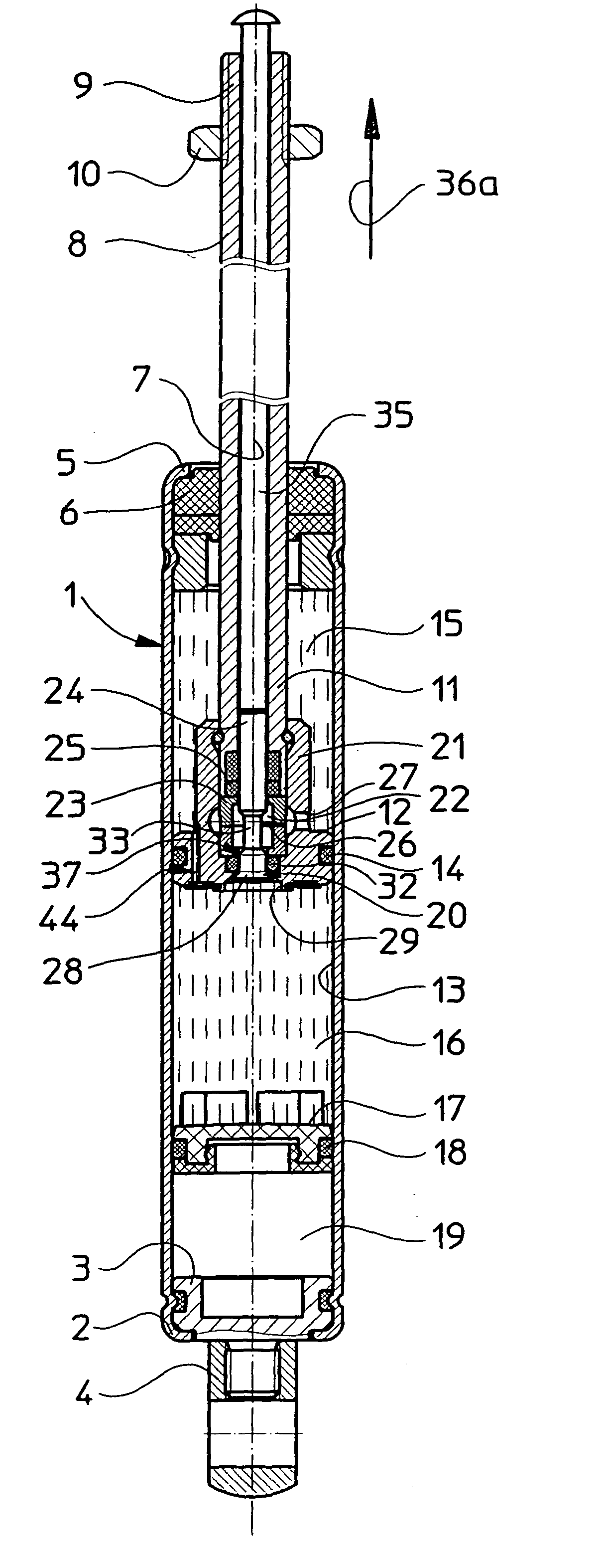
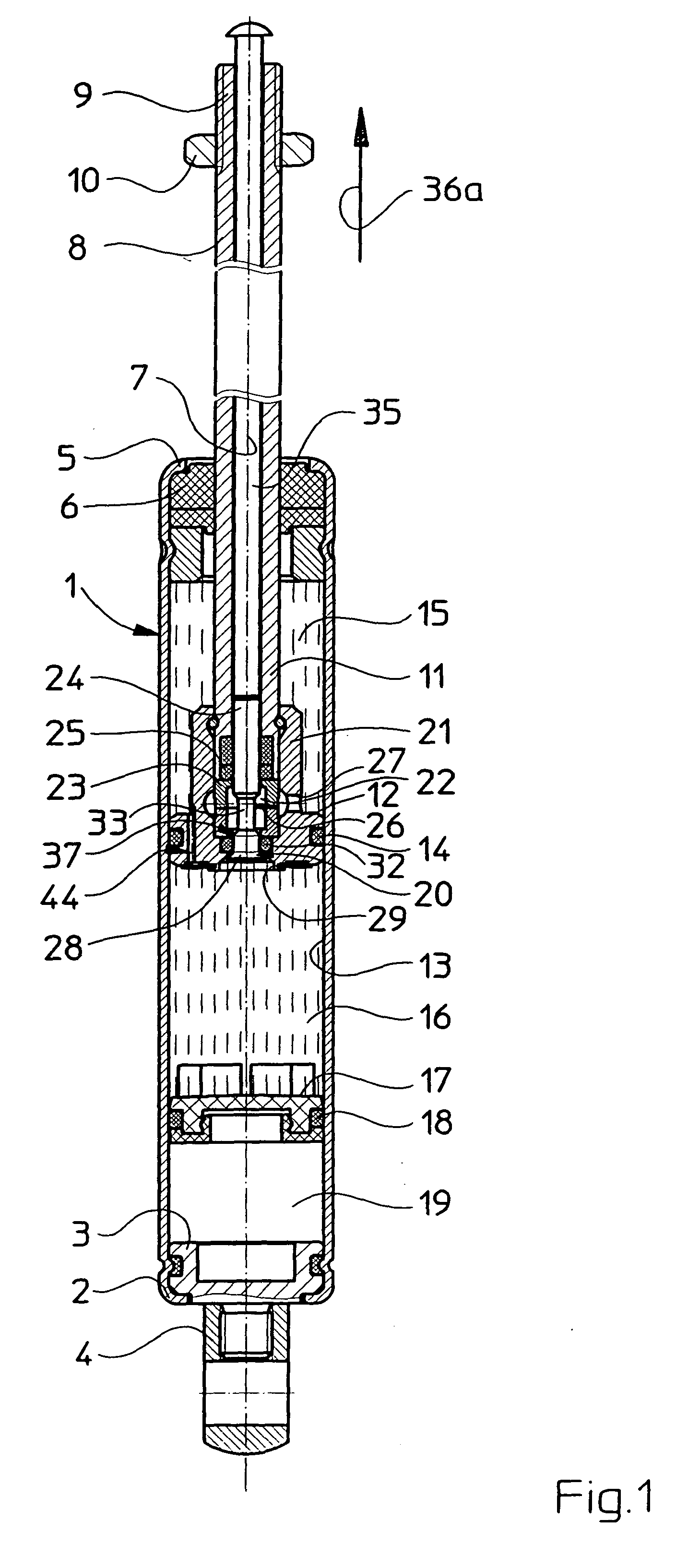
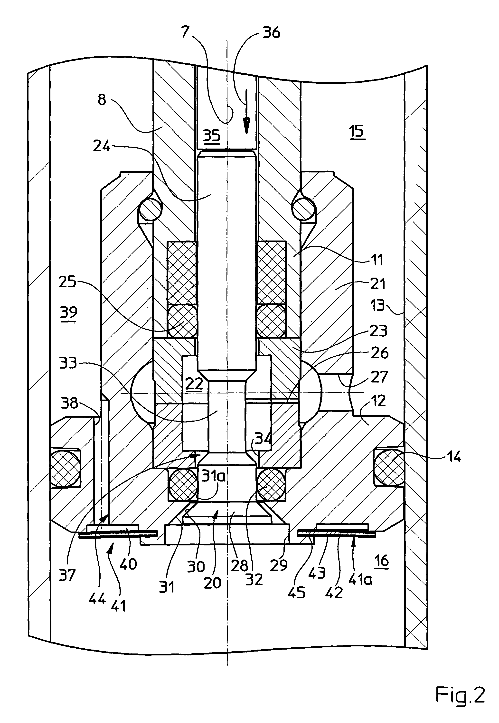
[0027] The first embodiment, seen in FIGS. 1 to 3, of a blockable, adjustable-length gas spring comprises a substantially cylindrical casing 1 in the form of a tube, one end 2 of which being sealed gastight by a bottom 3 on which is mounted a fastening element 4. An annular guide and seal unit 6 is fixed to the other end 5 of the casing 1 for fluid-tight sealing; the unit 6 serves for guiding and sealing a piston rod 8 which is displaceable in the casing 1 concentrically of the central longitudinal axis 7 thereof. Another fastening element 10 is mounted on the free end 9, outside the casing 1, of the piston rod 8.

[0028] A piston 12 is mounted on the end 1 1, inside the casing 1, of the piston rod 8; the piston 12 is guided on the inside wall 13 of the casing 1 and is made fluid-tight towards the wall 13 by the aid of a seal 14. The piston 12 divides the interior of the casing into a first sectional casing chamber 15, located between the piston 12 and the guide and seal unit 6, and a...

third embodiment

[0045] The piston 12 of the piston rod 8 is guided in an interior casing cylinder 48, which contains the second sectional casing chamber 16 and is disposed coaxially of an exterior casing cylinder 49 that defines the casing 1 outwards. In this embodiment, the piston 12 is not disposed between the two sectional casing chambers 15, 16. In the third embodiment, these two sectional casing chambers 15, 16 are separated by a blocking valve 50 with a valve body 51 that closes the interior casing cylinder 48 on the side turned towards the guide and seal unit 47. A seal 52 tightens between the valve body 51 and the inside wall of the interior casing cylinder 48.

[0046] On its end, turned towards the sectional casing chamber 16, the valve pin 24 of this embodiment comprises a pin section with a cylindrical sealing face 53. In the blocking-valve-50 shut-off position, this sealing face 53 rests on an opposite surface 55 of the valve body 51 via a seal 54. The actuation / overflow assembly 37 of th...


PUM


Abstract

A compression spring comprises a casing with a piston that is mounted on a piston rod being disposed for displacement therein. Two sectional casing chambers are provided in the casing, which are filled with pressure fluid and at least one of which is defined by the piston. A controllable first valve interconnects the sectional casing chambers in an open position and blocks the compression spring in a shut-off position. By way of an additional automatic valve between the sectional casing chambers, the compression spring, even when blocked, can be adjusted in the piston-rod push-out direction by a force being applied that is comparable to the push-out force that works in the push-out direction by the pressure of the pressure fluid. This provides for greater flexibility in use of the compression spring.

Description

[0001] 1. Field of the Invention[0002] The invention relates to an adjustable-length compression spring, comprising a casing, which is filled with a free-flowing pressure fluid and has a central longitudinal axis; a guide and seal unit, which closes a first end of the casing; a piston rod, which has an outer end and is sealingly extended through the guide and seal unit out of the first end of the casing; a piston, which is connected to the piston rod and sealingly guided in the casing; a pressure-fluid-filled first sectional casing chamber, which is unilaterally defined by the piston; an energy accumulator for exercising pressure on the pressure fluid; a pressure-fluid-filled second sectional casing chamber, which is connectable to the first sectional casing chamber; and a controllable valve for interconnection of the sectional casing chambers by an actuation / overflow assembly, the valve having a valve pin, which is movable from outside the casing into an open position of the contro...

Claims


Application Information

Patent Timeline
IPC IPC(8): F16F9/02F16F9/06F16F9/18F16F9/44F16F9/56
CPCF16F9/0272F16F9/44
Inventor RIEL, HANS-WERNERKNAPP, RAINERWUNDERLING, GERHARDRICHTER, STEFAN
Owner SUSPA
Why Eureka
Eureka Blog
Learn More