
Dielectric filter, communication apparatus, and method of controlling resonance frequency

a technology of dielectric filter and resonance frequency, which is applied in the direction of waveguide type device, coupling device, basic electric element, etc., can solve the problems of insufficient shielding of spurious signals, inability to achieve desired filter characteristics, and inability to pass through desired signals

Inactive Publication Date: 2004-03-04
PANASONIC CORP
View PDF17 Cites 13 Cited by
  • Summary
  • Abstract
  • Description
  • Claims
  • Application Information

AI Technical Summary

Problems solved by technology

However, the configuration described above has a disadvantage that an undesired resonance mode (spurious) other than a desired resonance mode (TE.sub.01.delta. resonance mode) occurs on the high-pass side of the filter pass band, thus allowing an undesired signal to pass through.
As apparent from FIG. 17, a conventional dielectric filter 1000 has a disadvantage that when a plate 1007 is brought close to the dielectric resonance element 1104 with the tuning means 1012 inserted therein (i.e. the insertion length of a bolt 1006 is increased), in particular, the spurious is close or identical to the resonance frequency of the TE.sub.01.delta. resonance mode, thus making it impossible to achieve desired filter characteristics.
Also, the conventional dielectric filter 1000 has a disadvantage that the spurious cannot be sufficiently shielded in the electromagnetic coupling between adjacent dielectric resonance elements with a coupling window 1010 formed by providing a space between a partition plate 1002 and the side face of the case 1001.
In addition, there is a disadvantage that the influence of the spurious also becomes significant in the electromagnetic coupling between dielectric resonance elements as a coupling adjusting screw 1009 is inserted into the coupling window 1010.

Method used


Image

  • Dielectric filter, communication apparatus, and method of controlling resonance frequency
  • Dielectric filter, communication apparatus, and method of controlling resonance frequency
  • Dielectric filter, communication apparatus, and method of controlling resonance frequency

Examples


embodiment 1

[0098] (Embodiment 1)

[0099] A dielectric filter of Embodiment 1 of the present invention will be described with reference to the drawings.

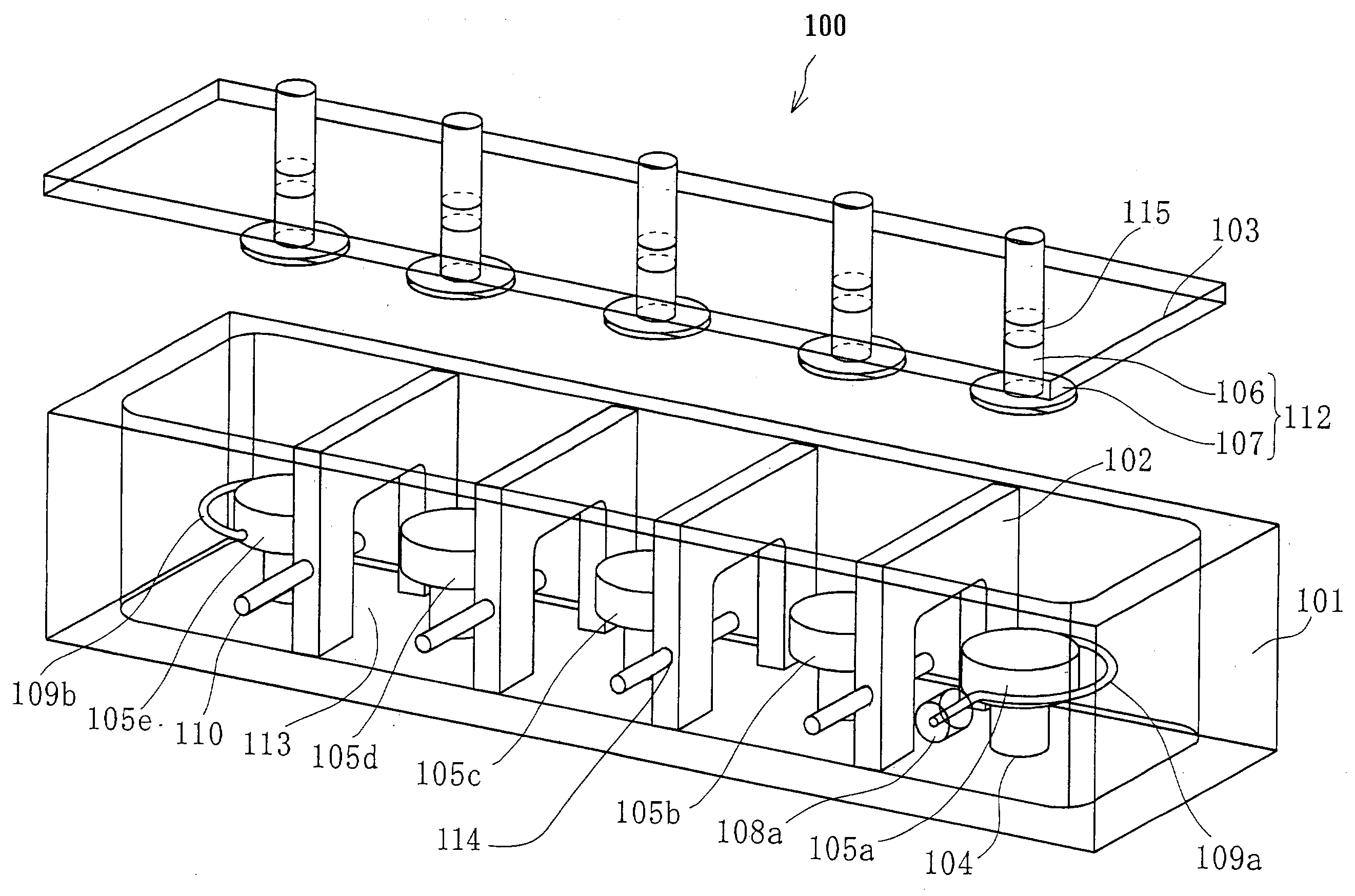
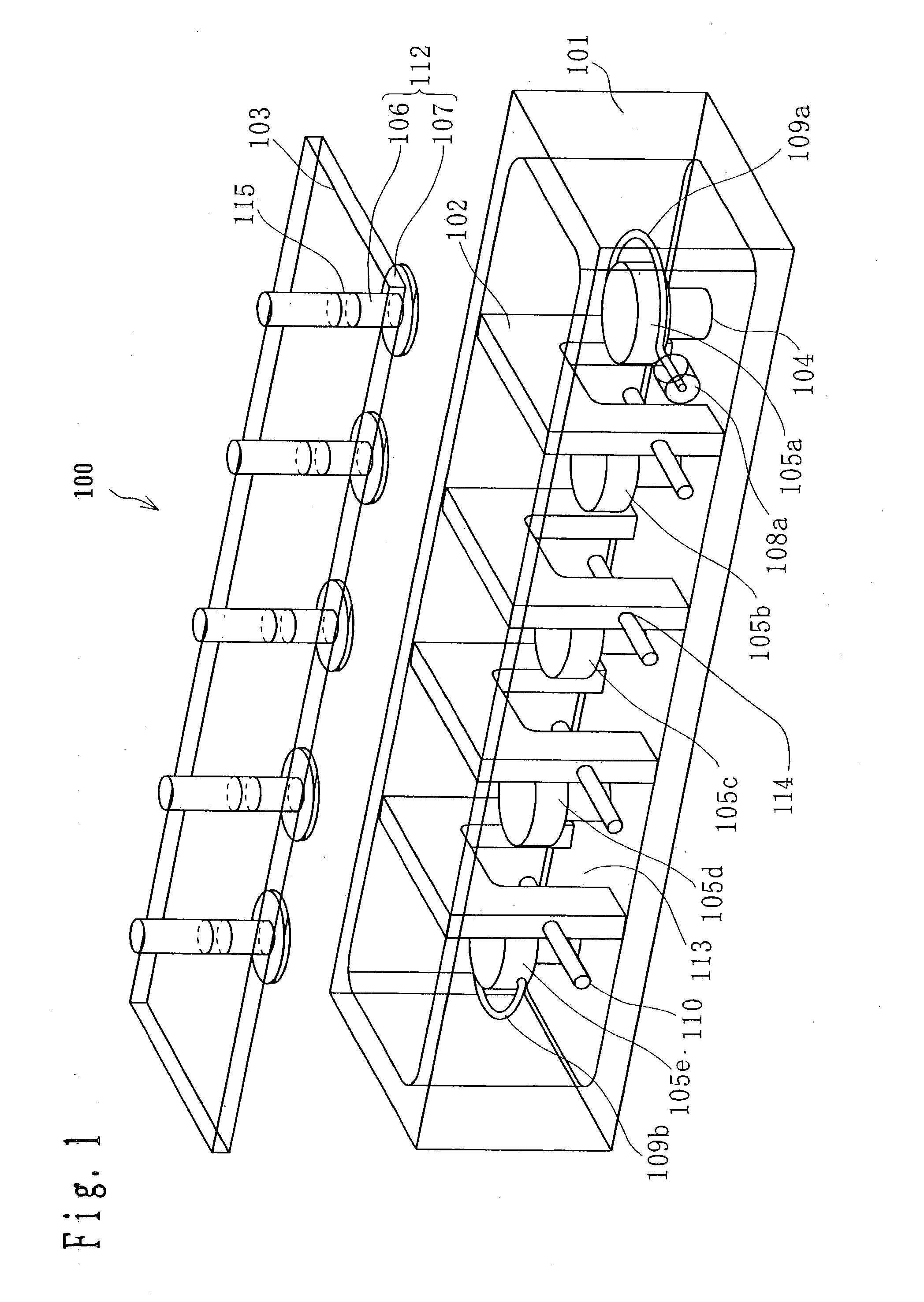
[0100] FIG. 1 is an exploded translucent perspective view of a five-stage TE.sub.01.delta. resonance mode bandpass filter (five-stage dielectric filter) 100 in Embodiment 1 of the present invention. In FIG. 1, the five-stage dielectric filter 100 comprises a case 101 being one example of the metal case of the present invention, a partition plate 102 being one example of the partition wall of the present invention, a lid 103 being one example of the metal lid of the present invention, a support 104, dielectric resonance elements 105a to 105e being one example of the dielectric resonance element of the present invention, tuning means 112, input / output terminals 108a and 108b (not shown), input / output probes 109a and 109b, and a coupling adjusting screw 110 being one example of the metal coupling adjusting member of the present invention.

[0101] The t...

embodiment 2

[0124] (Embodiment 2)

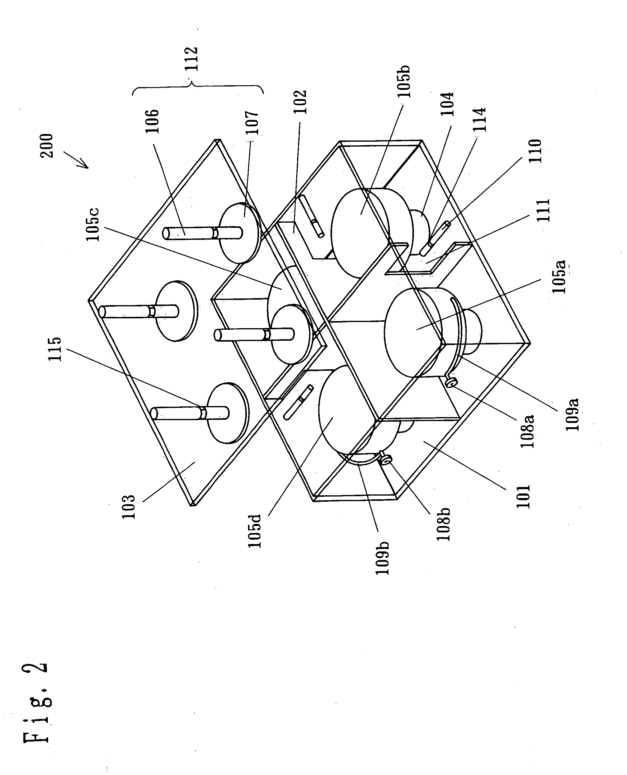
[0125] FIG. 2 is an exploded translucent perspective view of a four-stage TE.sub.01.delta. resonance mode bandpass filter (four-stage dielectric filter) 200 in Embodiment 2. In FIG. 2, components same as those of the five-stage dielectric filter 100 of Embodiment 1 are given like reference symbols, and the description thereof is omitted. The four-stage dielectric filter 200 of this embodiment comprises dielectric resonance elements 105a to 105d being one example of the dielectric resonance element of the present invention. In the four-stage dielectric filter of this embodiment, four cavities (spaces) are formed in such a manner that each cavity adjoins other two cavities by a case 101, a partition plate 102 placed in the case 101 and a lid 103, and the dielectric resonance elements 105a to 105d having flat upper faces are each mounted on the bottom face of the case 101 through a support 104 to be located at almost the center of each cavity.

[0126] In the partitio...


PUM


Abstract

The invention provides a dielectric filter including a metal case having an opening in the upper part, a metal lid of closing the opening, a dielectric resonance element placed on the internal bottom face of the case through a support, a bolt made of dielectric material inserted in a position in the lid corresponding to the dielectric resonance element, and a metal plate placed at the end of the bolt substantially in parallel with the upper face of the dielectric resonance element, wherein the position of the bolt is adjusted to change the space between the dielectric resonance element and the plate, whereby the resonance frequency is controlled.

Description

[0001] 1. Field of the Invention[0002] The present invention relates to a dielectric filter that is used in a mobile communication base station such as a cellular phone, a broadcast radio wave transmission station and the like, and a communication apparatus using the dielectric filter.[0003] 2. Related Art of the Invention[0004] In recent years, high-sensitivity send / receive characteristics and satisfactory speech quality have become essential in cellular phone systems, and low-loss passage characteristics with almost no degradation of signal components and steep-attenuation characteristics capable of reliably removing undesired disturbing wave components are required for filters in the base station. Filters satisfying such demands include a dielectric filter using a dielectric resonator having a high Q value (e.g. see James K. Plourde, Application of Dielectric Resonators in Microwave Components, "IEEE TRANSACTION ON MICROWAVE THEORY AND TECHNIQUES", IEEE, August, 1981 vol. MTT-29,...

Claims


Application Information

Patent Timeline
Patent Type & Authority Applications(United States)
IPC IPC(8): H01P1/208
CPCH01P1/2084
Inventor YAMAKAWA, TAKEHIKOISHIZAKI, TOSHIOTACHIBANA, MINORU
Owner PANASONIC CORP
Learn More