
Method for preventing counterfeiting or alteration of a prited or engraved surface

a technology for counterfeiting, which is applied in the field of methods for preventing counterfeiting or alteration of prited or engraved surfaces, which can solve the problems of striking visual differences between the original and the copying feature, difficult reproduction of special motifs and other decorative features, and appearance that disturbs the aesthetics of protected products

Active Publication Date: 2004-01-22
ALPVISION
View PDF44 Cites 19 Cited by
  • Summary
  • Abstract
  • Description
  • Claims
  • Application Information

AI Technical Summary

Benefits of technology

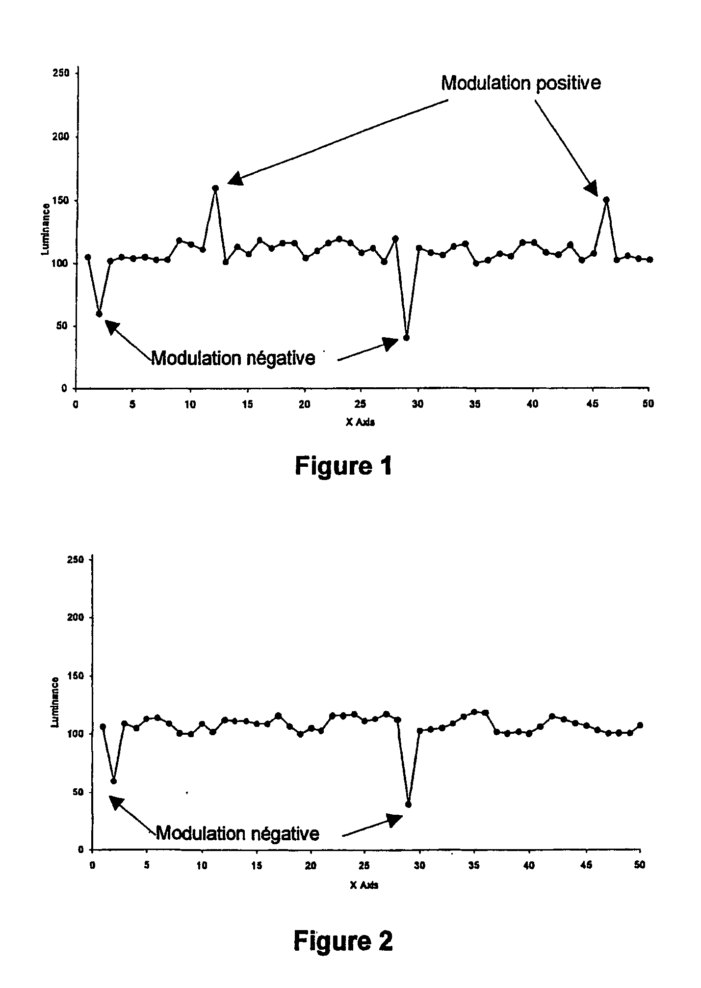
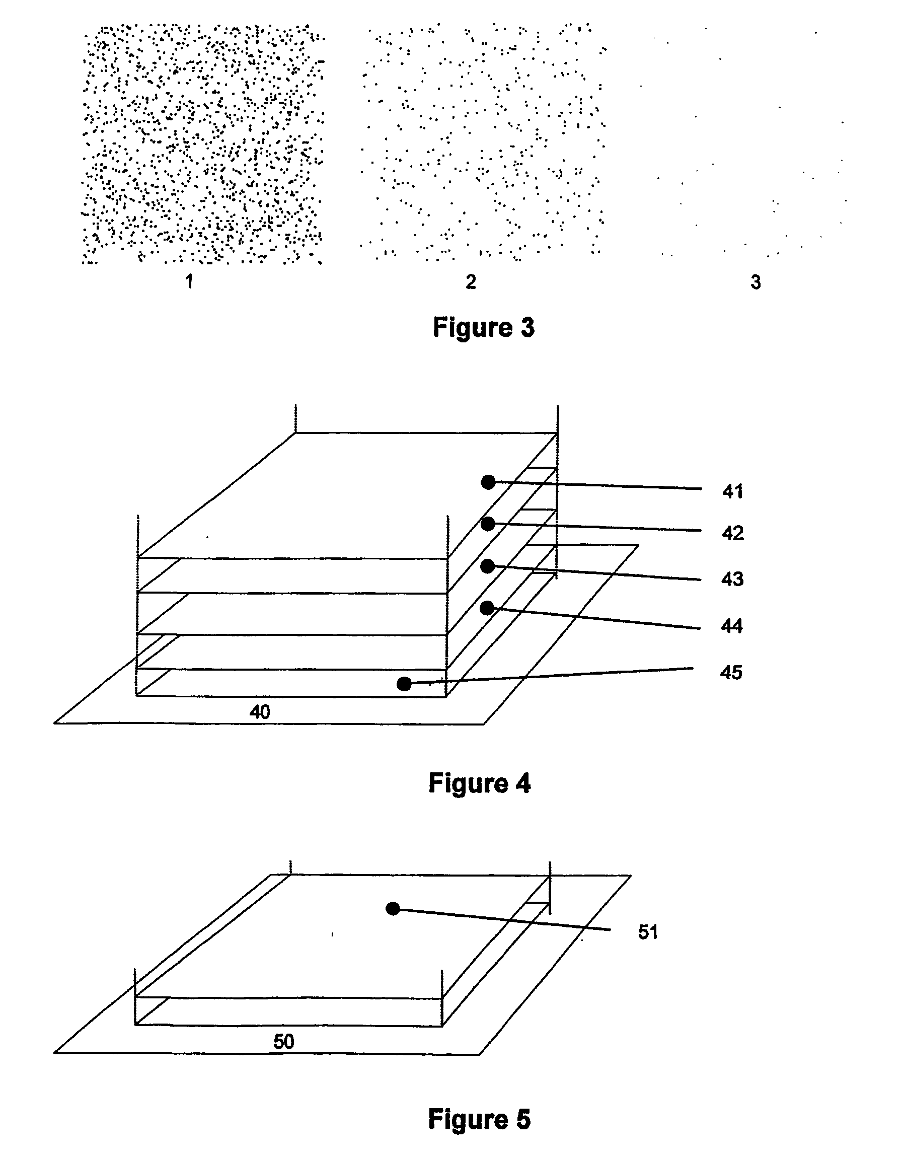
[0039] The present invention proposes to asymmetrically modulate the pixel colors. FIG. 2 shows an example of an asymmetric modulation obtained by darkening the color of certain pixels. The modulation can be positive or negative, depending on whether color is added or removed. The curve again shows the luminance variations of the pixels along the X-axis for a fixed position on the Y-axis. The two peaks illustrate the effect of an asymmetric modulation, obtained by only reducing the luminance. FIG. 3 gives some examples of digital marks.

Problems solved by technology

Holograms, special motifs and other decorative features are difficult to reproduce because they require special equipment.
They were specially designed to interfere with traditional copy systems so that the copy features significant visual differences from the original.
They can be verified through visual inspection without the help of particular devices but have the drawback of being expensive, sufficiently known to be reproduced by counterfeiting experts, and their visual appearance disturbs the aesthetic of the protected products (for example packaging of cosmetics).
The fact that these security features are visible also contributes to their limited efficiency because they can easily be identified by a counterfeiter and copied or physically removed.
In addition to the high price, these systems have two major disadvantages.
Firstly, due to the nature of the codes used, it is localized in a specific part of the document or packaging and can therefore easily be destroyed without altering the entire surface.
At last, systems based on memory or on-board processors have the disadvantage of being very expensive, not visually pleasing, and localized.
"imperceptible" means that the modifications introduced during the hiding process are such that it is not possible for a human to distinguish the original from the signed data with its own senses.
The problem consists in deriving a process allowing a computer to detect the hidden information, while it is not perceptible by our senses.
In the case where the mark is used to authenticate the surface relatively to copies, the robustness of the digital mark must be reduced such that a copy of the surface results in a failure of the detection of the mark.
Hence, it is not possible to erase it without altering the entire document, for example through scratching the surface.
In fact, malicious distributors often erase codes identifying their resellers (for instance invisible 2D codes) through milling the surface of the packaging where the code was applied.
In practice, this storage for example helps to secure information printed in visible text (and therefore prone to being modified).
This is essential because it significantly complicates forging a mark by a counterfeiter (the easiest approach is still copying an existing mark).
In addition, a counterfeiter is not able to verify the quality of a counterfeit because he does not know the key used to create the original mark.
Even when using special devices (filters, microscopes) it is difficult to identify a mark because it has a visual appearance that is similar to the paper grain.
The use of certain colors (e.g. yellow on a white paper) and high-resolution printing (e.g. 1200 dpi) makes it very difficult or impossible to copy the mark on classical copy equipment.
There exist certain cases where a symmetric modulation is not possible for either mathematical reasons (e.g. image to mark is entirely white or black) or practical reasons (related to the printing technology).

Method used


Image

  • Method for preventing counterfeiting or alteration of a prited or engraved surface
  • Method for preventing counterfeiting or alteration of a prited or engraved surface
  • Method for preventing counterfeiting or alteration of a prited or engraved surface

Examples


Embodiment Construction

[0041] The following description is given as an example and refers to the figures in the annex:

[0042] FIG. 1 illustrates an example of a symmetric modulation.

[0043] FIG. 2 illustrates an example of an asymmetric modulation.

[0044] FIG. 3 illustrates examples of an asymmetric mark.

[0045] FIG. 4 illustrates the implementation of the process integrated with offset printing technology.

[0046] FIG. 5 illustrates the implementation of the process with a separate offset printing step.

[0047] FIG. 6 illustrates the implementation of the process with a separate offset printing step.

[0048] FIG. 7 illustrates the implementation of the process with inkjet printer.

[0049] FIG. 8 shows a block diagram of a process to sign a material in three steps.

[0050] FIG. 9 shows a block diagram of a reading process of a uniform image signed in three steps.

[0051] FIG. 10 shows a block diagram of a reading process of a non-uniform image signed in three steps.

[0052] An example of a symmetric modulation is illustrat...


PUM


Abstract

The invention describes a process to prevent counterfeiting or alteration of a printed or engraved surface, characterized by the incorporation of a signature of the form of a digital mark into parts or the entire document, and in particular a digital mark technology to hide information in an invisible way through over-printing by using a method called asymmetric amplitude modulation. This method can be applied to any type of printed material such paper, packaging, or any other surface. Visible information can also be printed over the digital mark. As an application example, applied to a paper document the digital mark can be used to guarantee the document authenticity, as it would be destroyed by a copy process.

Description

[0001] The present invention proposes a method for preventing counterfeiting or alteration of a printed or engraved surface.STATE OF THE ART[0002] Common systems for the prevention of counterfeiting or alteration of printed or engraved documents can be grouped as follows:[0003] Holograms, printing of special motifs[0004] Printing with special inks[0005] Codes using invisible inks[0006] Systems using a digital chip[0007] Holograms, special motifs and other decorative features are difficult to reproduce because they require special equipment. They were specially designed to interfere with traditional copy systems so that the copy features significant visual differences from the original. They can be verified through visual inspection without the help of particular devices but have the drawback of being expensive, sufficiently known to be reproduced by counterfeiting experts, and their visual appearance disturbs the aesthetic of the protected products (for example packaging of cosmetic...

Claims


Application Information

Patent Timeline
Patent Type & Authority Applications(United States)
IPC IPC(8): G07D7/004G07D7/005
CPCG07D7/008G07D7/004G07D7/0056
Inventor JORDAN, FREDERICMEYLAN, ROLANDKUTTER, MARTIN
Owner ALPVISION
Learn More