Eureka AIR delivers breakthrough ideas for toughest innovation challenges, trusted by R&D personnel around the world.

Ultrasonic cannula system

Inactive Publication Date: 2004-01-08
PAUBO
View PDF9 Cites 119 Cited by
  • Summary
  • Abstract
  • Description
  • Claims
  • Application Information

AI Technical Summary

Problems solved by technology

There are attendant risks of rupture of the inflated balloon while it is within the vertebrae.

Method used


Image

  • Ultrasonic cannula system
  • Ultrasonic cannula system
  • Ultrasonic cannula system

Examples


Embodiment Construction

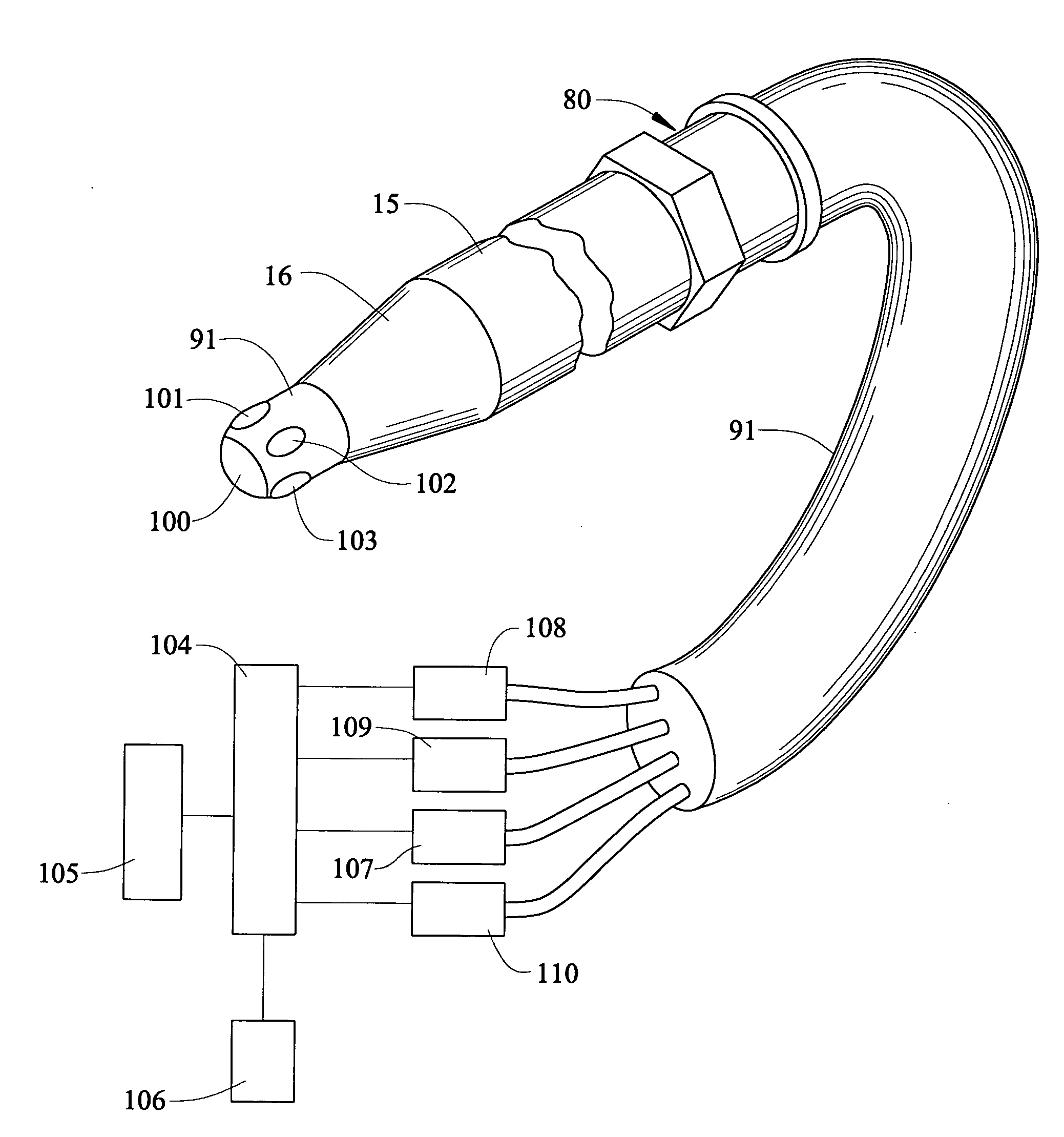
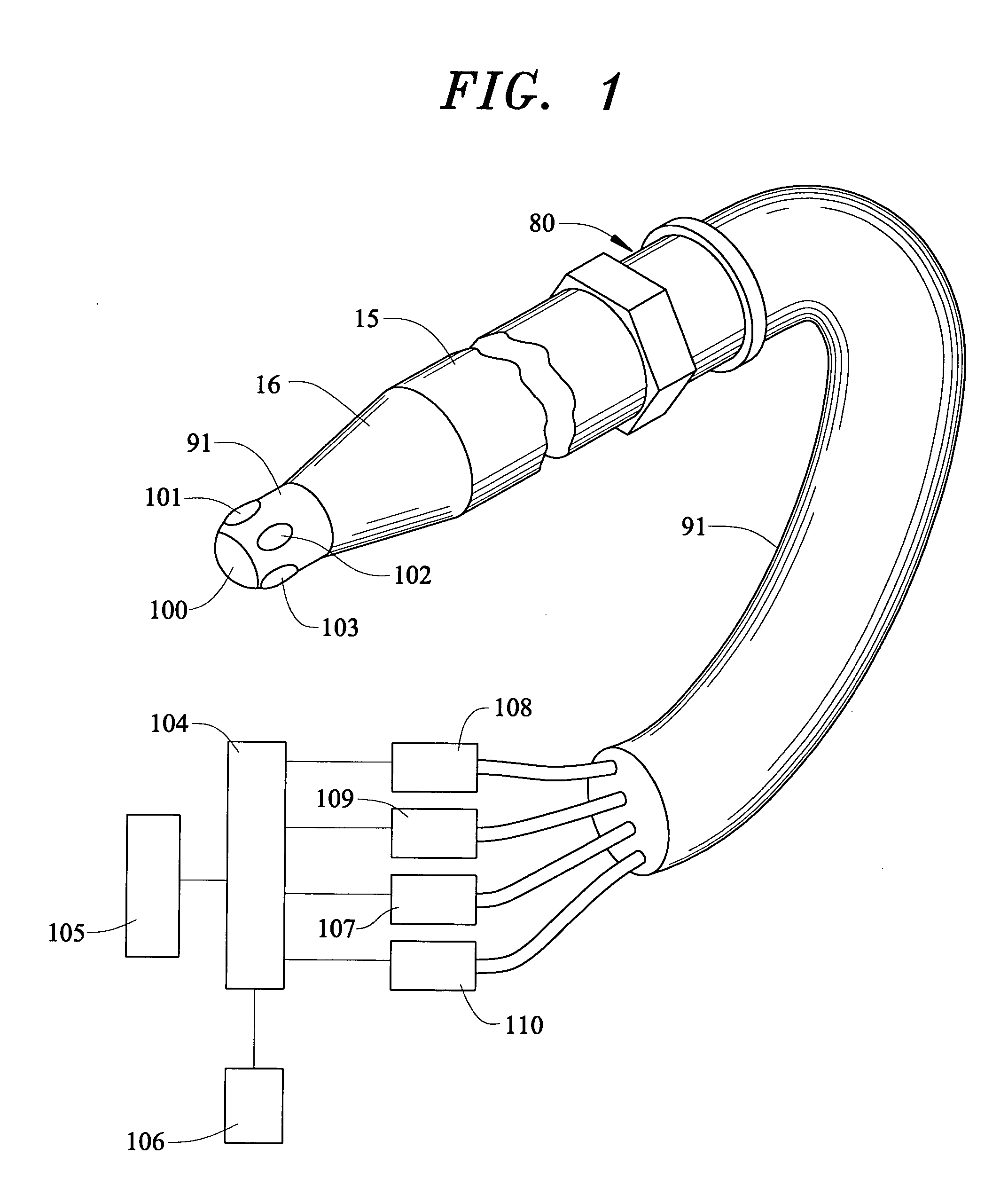
[0031] The ultrasonic surgical system, shown in FIG. 1, may have different utilitarian features, eg., the entire system may be housed in a free standing cabinet, either fixed or mobile. The system may be enclosed in a wall mounted or a table top cabinet. Or the different components could be separate and connected only by the various leads and tubes necessary for functional operation. Depending on the particular surgery to be performed and / or the anatomical location of the surgery, the system may be operated with less than all the components or some components inactive.

[0032] The leading end 91 of the tubular surgical implement is equipped to deliver ultrasonic energy, inject biological material, aspirate, and view the surgical field. Of course, these functions could be done sequentially through a single lumen in a catheter or the catheter can have multiple channels for simultaneous functions. As shown in FIG. 1, the ultrasonic energy is delivered by a transducer 100, the delivery of...


PUM


Abstract

A surgical kit for inserting a biological material into a portion of the skeletal bone by a minimally invasive technique has several components which are manually operated using a universal tool. The kit includes a docking needle used as a guide for placing a cannula in a bone. The tool has a spring loaded hinged connection for temporarily attaching to the other components and which locks upon release of compression. An ultrasonic probe is inserted through the cannula for forming a cavity within the soft tissue of the bone. Treatment or support material is placed in the cannula and a plunger is inserted in the cannula. The universal tool is connected to the plunger and the material is expelled by telescopic movement of the plunger.

Description

[0001] This application is a continuation-in-part of application Ser. No. 10 / 190,044, the entire contents of which are herein incorporated by reference.[0002] This invention relates to orthopedic surgery and to an ultrasonic apparatus and process for minimal invasion of skeletal bones in the body for treatment and support.[0003] The use of cannulas to gain access to the interior regions of a patient's body is very old. In recent history, the use of the cannula in all types of surgery has gained wide acceptance. Heart catheterization and delivery of stints contributed to the increased popularity, as well as laproscopic surgery of all kinds. These techniques have reduced patient trauma, incidence of infection and hospital stays. These procedures have in common gaining access to the interior of the body by a small stab wound through which is inserted a cannula for maintaining a passageway. All sorts of other surgical implements may then traverse this passageway depending on the specifi...

Claims


Application Information

Patent Timeline
IPC IPC(8): A61B8/12A61B17/00A61B17/22A61B17/32A61B17/34A61B17/88
CPCA61B8/12A61B17/00234A61B17/22012A61B17/320068A61B17/3421A61B2017/22015A61B17/8816A61B17/8819A61B2017/00261A61B2017/0046A61B2017/00469A61B17/3472A61B10/025A61B2010/0258
Inventor SPROUL, MICHAEL E.
Owner PAUBO
Why Eureka
Eureka Blog
Learn More