
Patterned supports for testing, evaluating and calibrating detection devices

a detection device and support technology, applied in the direction of instruments, nanoinformatics, analysis using chemical indicators, etc., can solve the problems of difficult comparison, serious difficulties in comparing and coordinating the results of different uses, and cost of processing

Inactive Publication Date: 2004-01-08
MULHERN GREGORY +2
View PDF4 Cites 30 Cited by
  • Summary
  • Abstract
  • Description
  • Claims
  • Application Information

AI Technical Summary

Benefits of technology

[0017] Accordingly, this invention provides a simple reusable patterned support for conducting low-cost diagnostics and / or quality control of microarray detection devices, in contrast with the problems inherent in microarray spotting devices.

Problems solved by technology

Without the desired degree of calibration, it becomes difficult to compare the results obtained from biological testing, research or other uses performed with the same instrument utilizing different fluorescent labels, or to differentiate between results obtained on different instruments, thus creating serious difficulties in comparing and coordinating the results of different uses, or of different iterations within the same use.
One shortcoming of this technology is the cost of the processing.
The difficulty with this method is that the glass slide fluoresces over a great thickness.
The fluorescent radiation emitted throughout this thickness makes focusing difficult.
Several inherent problems arise from the use of printed microarrays as evaluation or diagnostic tools.
Arrays such as these are subject to inconsistent spot size, inconsistent spot positioning, inconsistent spot volume, and inconsistent density of spotted fluorophores.
These problems stem from difficulties arising during fabrication of the printed microarrays, including print positioning due to mechanical tolerance of the system, print quality due to the sample application device, and sample impurity due to chemical synthesis errors.
The efficiency of the method is often not constant.

Method used


Image

  • Patterned supports for testing, evaluating and calibrating detection devices
  • Patterned supports for testing, evaluating and calibrating detection devices
  • Patterned supports for testing, evaluating and calibrating detection devices

Examples


Embodiment Construction

[0033] As described above, the present invention is directed to compositions and methods for testing, evaluating, and calibrating detection devices. Various parameters that can be assessed include detection limit, sensitivity, scan speed, image resolution, dynamic range, as well as other characteristics.

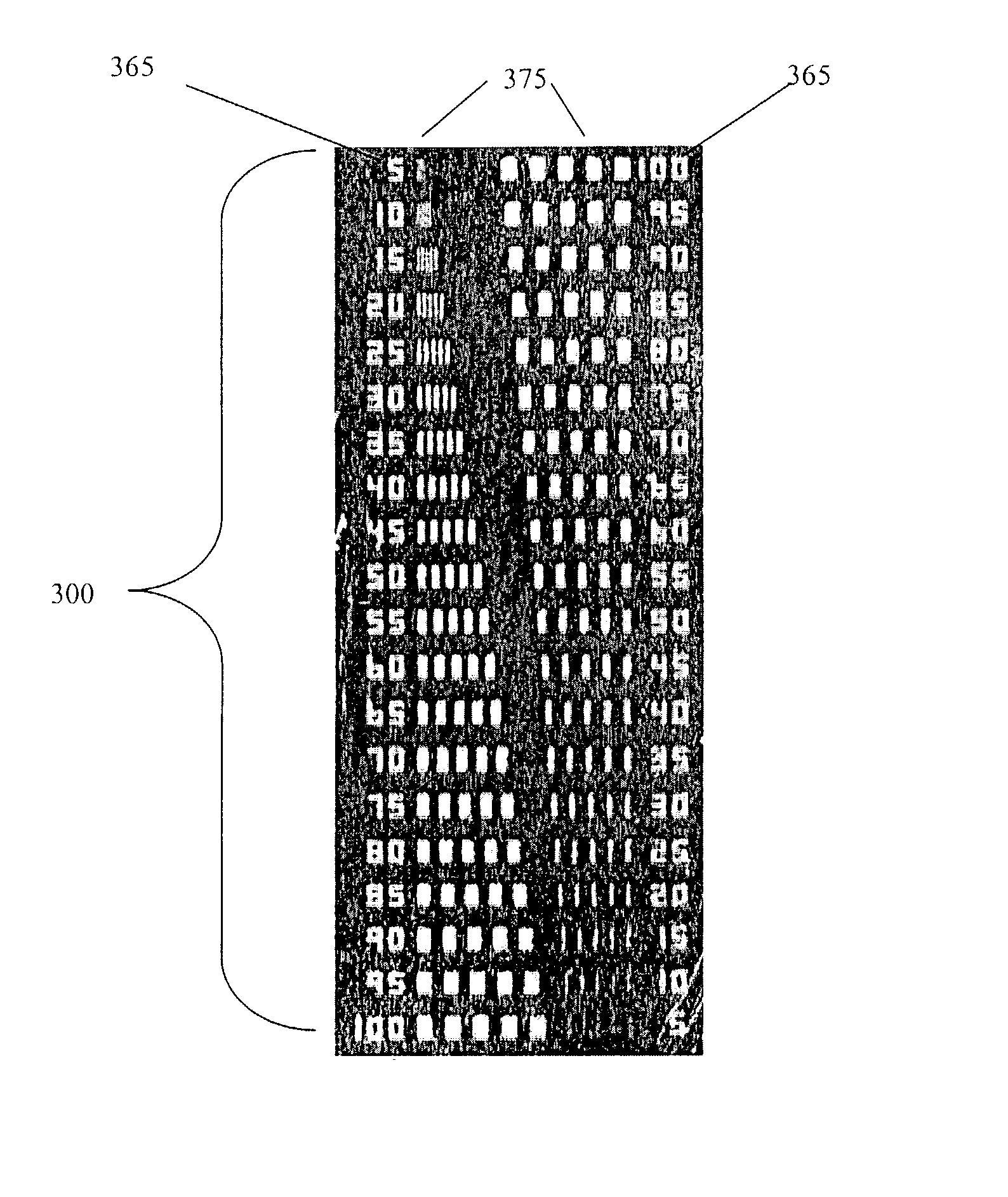
[0034] In one embodiment, the invention provides a non-uniform patterned support comprising a plurality of features wherein the features are used for evaluation of a detection device. In some embodiments, the features comprise a non-uniform pattern or patterns of detectable substance on the support. The non-uniform pattern or patterns of detectable substance can be useful to determine the device's ability to resolve images of differing sizes and spacing (see FIG. 5). For example, if it is known that an accurate detection device resolution of 5 microns is essential for the experiments to be performed, a support can be patterned that has features to test the ability of the device to re...


PUM

PropertyMeasurementUnit
Compositionaaaaaaaaaa
Sensitivityaaaaaaaaaa
Fluorescenceaaaaaaaaaa

Abstract

Compositions for testing, evaluating and calibrating detection instruments and methods for making such compositions are described. The compositions comprise a testing feature or plurality of testing features wherein the testing feature or plurality of testing features comprise a detectable substance and are used to evaluate the performance of a detection device. The compositions are useful for analyzing detection limits, sensitivity, image resolution, dynamic range and other parameters. They can also be used to compare data generated by different instruments, in different labels, in different labs or with different optics.

Description

[0001] This application claims the benefit of U.S. Provisional Application 60 / 361,715 filed on Mar. 6, 2002.[0002] 1. Field of Invention[0003] This invention is directed to methods for fabricating patterned supports for testing, evaluating and calibrating detection instruments. This invention is also directed to patterned supports produced by such methods.[0004] 2. Description of Related Art[0005] Microarrays include arrays of active spots and are available in a variety of forms. Generally, detection of analytes associated with cognate spots is accomplished using one or more fluorescent labels. The reagents involved in the chemical reactions in the active spots of the array are typically biological samples such as DNA, RNA, peptides, proteins or other organic molecules. Microarrays can be used for diagnostics, screening assays, genetics and molecular biology research.[0006] Supports comprising microarrays are often processed in a device that illuminates the spots comprising labeled ...

Claims


Application Information

Patent Timeline
IPC IPC(8): G01N21/27
CPCB82Y10/00Y10T428/24802G01N21/278B82Y20/00
Inventor MULHERN, GREGORYPOWELL, STEPHENLATIMER, DARIN
Owner MULHERN GREGORY
Learn More