
Door module for a vehicle door, vehicle door comprising a door module as well as method of mounting a door module to a vehicle door

Inactive Publication Date: 2007-07-19
ARVINMERITOR GMBH
View PDF0 Cites 21 Cited by
  • Summary
  • Abstract
  • Description
  • Claims
  • Application Information

AI Technical Summary

Benefits of technology

[0006]According to a first aspect of the invention, a door module for a vehicle door is provided for this purpose. The door module comprises a module plate and a window lifter rail attached to the module plate. The window lifter rail is movable in translation, is pivotally attached to the module plate, and is fixed by an easily detachable retaining mechanism in a supply position. Due to the fact that the window lifter rail is both movable in translation and pivotally supported on the module plate, the window lifter rail can be immobilized, in particular, in a supply position in which only one end of the window lifter rail protrudes beyond an edge of the module plate. This allows a comparably simple insertion of the window lifter rail into an opening of the vehicle door, with the retaining mechanism making sure that the window lifter rail does not perform any undesired movement in the meantime.
[0007]Preferably, the easily detachable retaining mechanism is a cable retainer that engages the window lifter rail, and engages a protrusion or an opening of the module plate. As a mass-produced article, such a cable retainer represents a particularly low-cost and yet effective retaining mechanism. When the cable retainer engages an opening of the module plate, there is the further advantage that the cable retainer can also be removed from a dry area side of the module plate, i.e. a side facing away from the window lifter rail. Consequently, the cable retainer can be detached without any problems after the module plate has been put onto the opening in the vehicle door, and closes this opening at least to a large extent.
[0011]The above described, movable and pivotable supporting of the window lifter rail on the module plate can be achieved in a particularly simple way. In one example, the window lifter rail has an elongated hole that is engaged by a stud attached to the module plate. With a module plate made of plastic, the stud is integrally formed with the module plate. It would also be possible, of course, that the module plate has the elongated hole which is engaged by a bolt connected with the window lifter rail, with the former variant presenting advantages in respect of the separation of wet and dry area sides.
[0012]The problem of the invention is also solved by a vehicle door comprising a door module. The vehicle door includes an inner wall provided with an opening that has an upper and a lower edge, an opening for a fastening bolt of a window lifter rail being provided on one of these edges, and a unilaterally opened slit for a fastening bolt of the window lifter rail being provided at the other edge. The window lifter rail is fastened to the inner wall by two fastening bolts in a region of the upper and lower edges. With this design, only one of the fastening bolts will be put through the associated opening in the inner wall of the vehicle door, while the other fastening bolt is laterally inserted in the unilaterally opened slit in a simple and time-saving manner. This results in a particularly simple fastening mechanism for the door module.
[0018]According to a preferred embodiment, the immobilizing of the second end of the window lifter rail is carried out by laterally shifting the module plate. This is accomplished by the second fastening element, which is attached to the window lifter rail, laterally engaging a counter piece attached to the inner wall of the vehicle door. Thus, the second end of the window lifter rail will be automatically immobilized, further simplifying the installation process.

Problems solved by technology

In the functional position of the window lifter rail, this bolt may engage a counter piece attached to an inner wall of the vehicle door, thereby immobilizing the window lifter rail.

Method used


Image

  • Door module for a vehicle door, vehicle door comprising a door module as well as method of mounting a door module to a vehicle door
  • Door module for a vehicle door, vehicle door comprising a door module as well as method of mounting a door module to a vehicle door
  • Door module for a vehicle door, vehicle door comprising a door module as well as method of mounting a door module to a vehicle door

Examples


Embodiment Construction

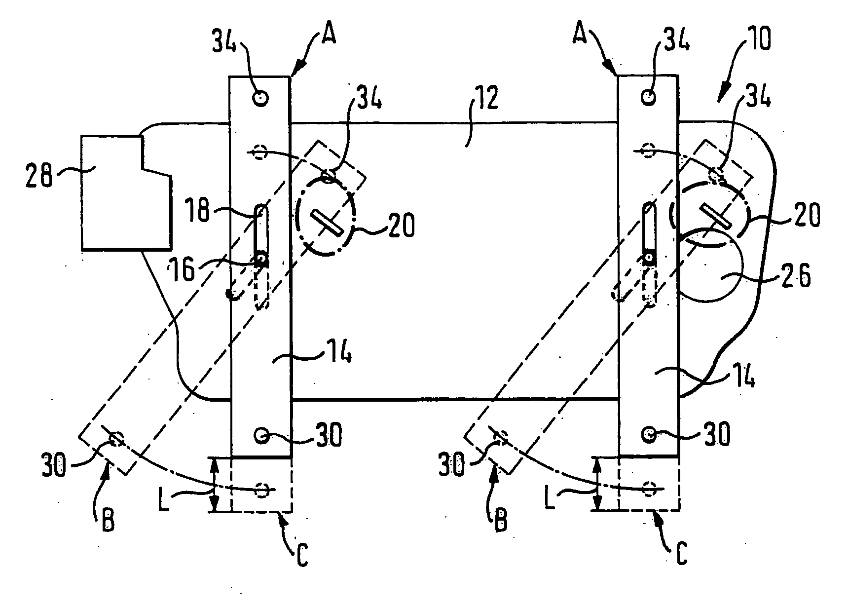
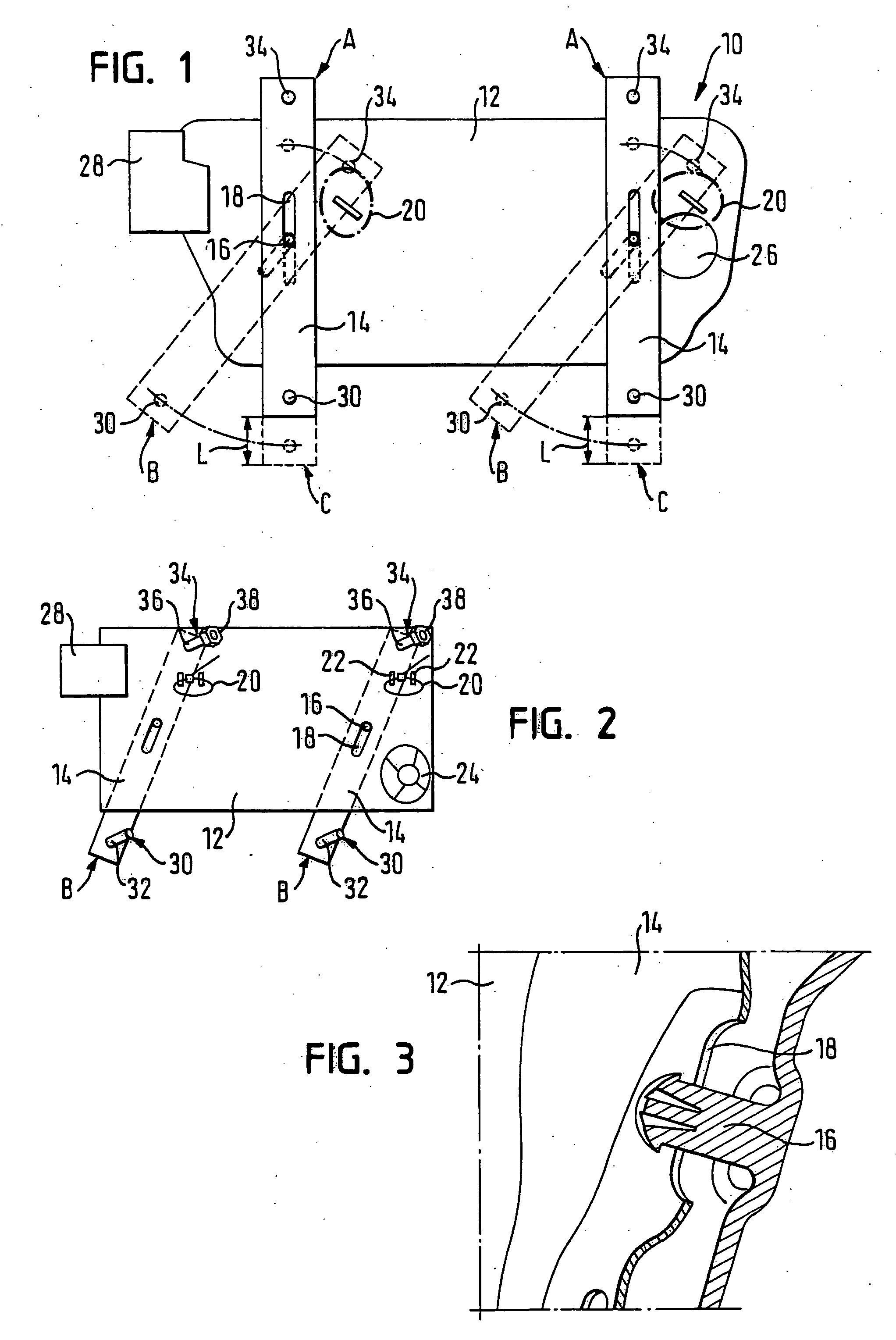
[0034]FIG. 1 shows a door module 10 that is to be mounted to a vehicle door. The door module 10 has a module plate 12 and two window lifter rails 14, which are shown in FIG. 1 both in a vertical functional position A (solid lines) and in a supply position B (broken lines) swiveled with respect to the functional position. To attach the window lifter rails 14, the module plate 12 is provided with one stud 16 for each window lifter rail 14. The studs 16 are integrally connected with the module plate 12 and engage an elongated hole 18 of a respective window lifter rail 14 (see also FIG. 3). In this way, both window lifter rails 14 are movable in translation and are pivotally connected with the module plate 12.

[0035]Next to the functional position A and the supply position B, there is further indicated in FIG. 1 a (theoretical) intermediate position C. In this position, the window lifter rails 14 extend in a vertical direction, but are shifted downward compared with the functional positi...


PUM


Abstract

The invention relates to a door module for a vehicle door that includes a module plate and a window lifter rail attached to the module plate. The window lifter rail is movable in translation, is pivotally attached to the module plate, and is fixed by an easily detachable retaining mechanism in a supply position. The invention further relates to a vehicle door comprising such a door module as well as to a method of mounting a door module to a vehicle door.

Description

RELATED APPLICATIONS[0001]The application claims priority to German Application No. 10 2006 002 406.0, which was filed on Jan. 18, 2006.BACKGROUND OF THE INVENTION[0002]The invention relates to a door module for a vehicle door as well as to a vehicle door comprising such a door module. The invention further relates to a method of mounting a door module to a vehicle door.[0003]Modern vehicle doors typically are equipped with numerous functional components, for instance a window lifter system with at least one window lifter rail, a door lock, loudspeaker, etc. For the purpose of saving time, these functional components are not individually mounted to an inner side of the vehicle door, but are pre-assembled on a plate to provide a door module. The pre-assembled door module is subsequently fastened to the inner wall of the vehicle door. It is preferred that a module plate of the door module completely closes an opening in the inner wall of the vehicle door, which serves to accommodate t...

Claims


Application Information

Patent Timeline
IPC IPC(8): E05F11/38
CPCB60J5/0416B60J5/04B60J5/00B60J1/17E05F11/44
Inventor HEYER, THOMASBIGOURDEN, JEAN-FRANCOIS
Owner ARVINMERITOR GMBH
Learn More