
Optical sampling measurement apparatus and optical sampling measurement method

Inactive Publication Date: 2003-12-04
ANDO ELECTRIC CO LTD
View PDF2 Cites 5 Cited by
  • Summary
  • Abstract
  • Description
  • Claims
  • Application Information

AI Technical Summary

Benefits of technology

[0011] According to the present invention, the storage unit previously stores the noise which is generated in the light receiving element. On measuring the light to be measured, the noise is obtained by subtracting the light receiving element noise stored in the storage unit, from the measured noise, in order to calculate the Q value of the light to be measured. Accordingly, it is possible to accurately measure the Q value of the light to be measured, even though the inputted light of the light receiving element has a weak intensity on the basis of the nonlinear optical effect and the noise generated in the light receiving element wields a very large influence over the measurement of the light to be measured, inasmuch as the influence of the noise generated in the light receiving element is removed from the measured noise.

Problems solved by technology

There are a thermal noise and a shot noise each of which is generated in the light receiving element and there is an amplifier noise which is generated in an amplifier for amplifying an photoelectric current outputted from the light receiving element, as the noises generated in the optical sampling measurement apparatus.
More particularly, a power of the light (sum frequency light wave), which is inputted to the light receiving element, becomes very weak, in the optical sampling measurement apparatus using the nonlinear effect.
As a result, the ratio of noise becomes great in comparison to the received light signal which is obtained by receiving the light to be measured.
It is difficult to accurately measure the variance of signal levels of the light to be measured.
Therefore, it is difficult to accurately measure the Q value of the light to be measured.
In addition, the storage unit stores the noise generated in the light receiving element at each light intensity of the light to be measured, in the light sampling measurement apparatus.

Method used


Image

  • Optical sampling measurement apparatus and optical sampling measurement method
  • Optical sampling measurement apparatus and optical sampling measurement method
  • Optical sampling measurement apparatus and optical sampling measurement method

Examples


Embodiment Construction

[0019] With reference to drawings, a detailed description will be made as regards a light sampling measurement apparatus and a light sampling measurement method according to a preferred embodiment of the present invention.

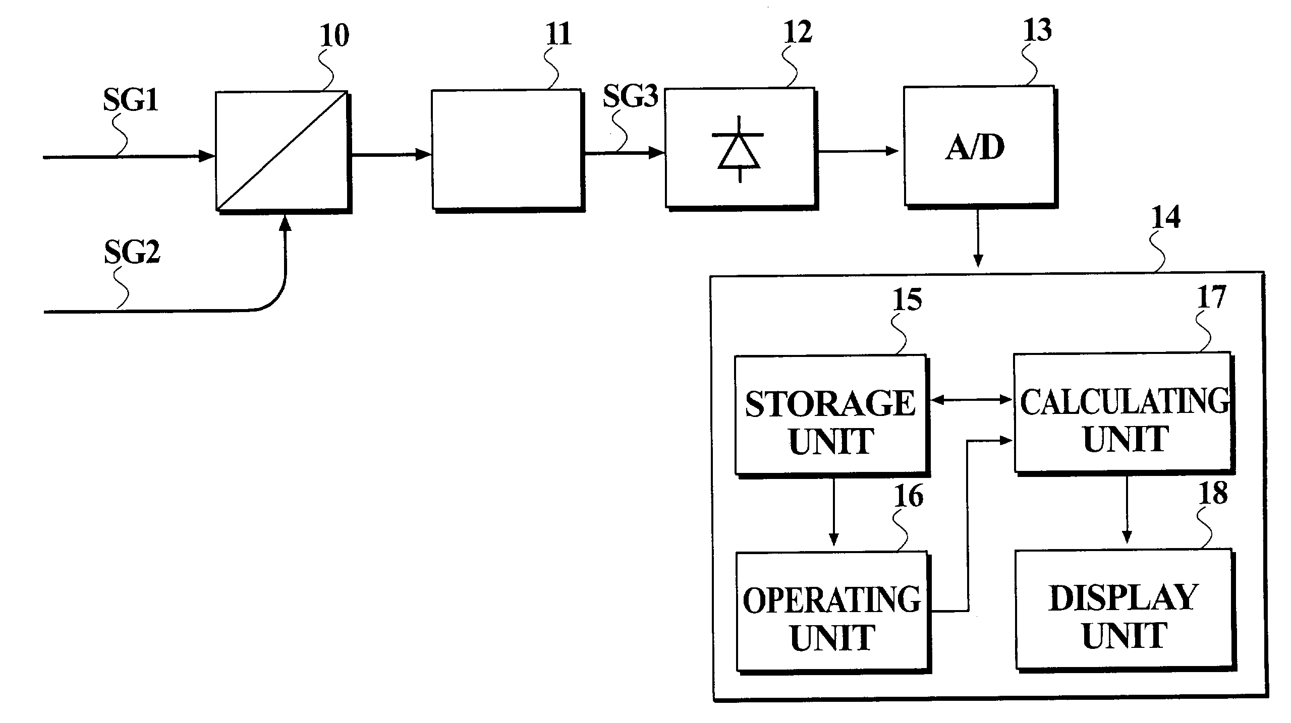
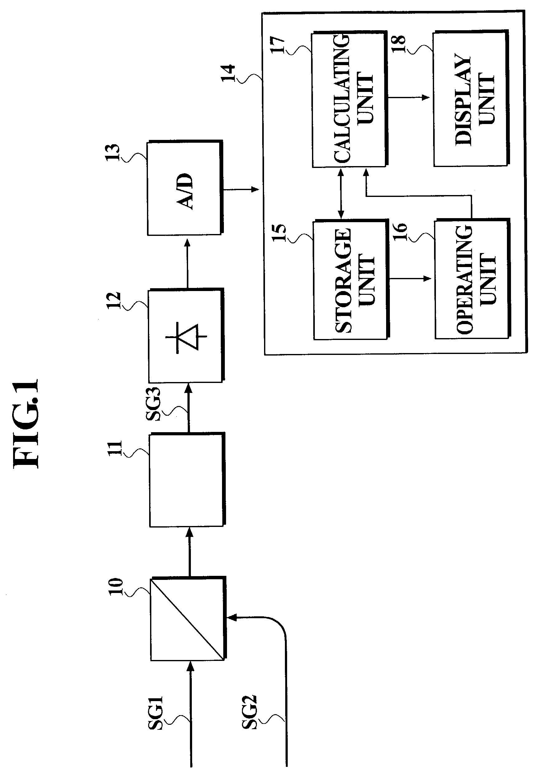
[0020] FIG. 1 is a block diagram for illustrating schematic configuration of a light sampling measurement apparatus according to a preferred embodiment of the present invention. As shown in FIG. 1, the light sampling measurement apparatus according to the preferred embodiment comprises an optical wave multiplexer 10, a nonlinear optical element 11, a light receiving element 12, an A / D converter 13, and a signal processing section 14.

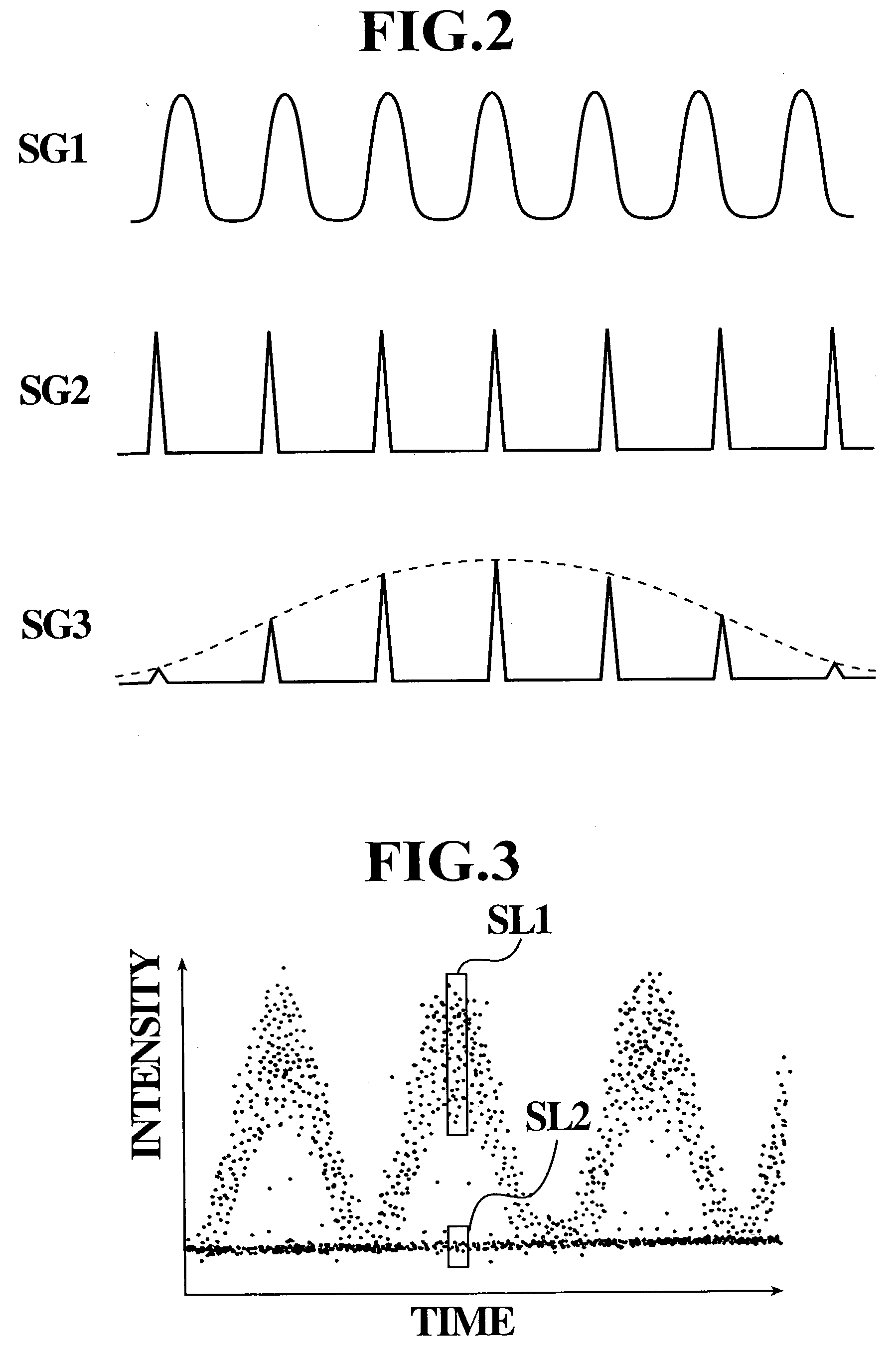
[0021] The optical wave multiplexer 10 multiplexes a light SG1 to be measured and a sampling light SG2 to output a multiplexed light. The nonlinear optical element 11 is, for example, phosphoric titanic potassium (KTiOPO.sub.4). The nonlinear optical element 11 has an optical axis defined so as to generate a sum frequency light SG3 obta...


PUM


Abstract

A light sampling measurement apparatus comprising a nonlinear optical element supplied with a light to be measured and a sampling light and a light receiving element for receiving a light outputted from the nonlinear optical element, includes: a storage unit for previously storing noise generated in the light receiving element; a calculating unit for obtaining a subtracted noise by subtracting the noise stored in the storage unit, from a measured noise, to calculate a Q value of the light to be measured.

Description

[0001] 1. Field of the Invention[0002] The present invention relates to an optical sampling measurement apparatus and an optical sampling measurement method of carrying out sampling of a light to be measured, using a nonlinear optical effect to measure a waveform or the like of the light to be measured.[0003] 2. Description of the Related Art[0004] Recently, optical communication technology exponentially evolves and a light sampling measurement apparatus actively develops which measures a waveform or the like of optical pulse propagating through an optical fiber for use in an optical transmission path, with evolution of optical communication technology. Proposal is made about a light sampling measurement apparatus which receives the light to be measured and a pulsed sampling light having a (temporally) narrow width, by a nonlinear optical element and which generates a sum frequency light wave in the nonlinear optical element, as a kind of light sampling measurement apparatus. The li...

Claims


Application Information

Patent Timeline
IPC IPC(8): G01J11/00G02F1/37
CPCG01J11/00
Inventor YANAGISAWA, YOSHIKIKANZAKI, MASATOSHI
Owner ANDO ELECTRIC CO LTD
Learn More