
Wave powered cyclic anchoring itinerant ship propulsion system

Inactive Publication Date: 2003-11-27
GORSHKOV VLADISLAV VASILYEVICH
View PDF0 Cites 50 Cited by
  • Summary
  • Abstract
  • Description
  • Claims
  • Application Information

AI Technical Summary

Benefits of technology

0029] 9. A glider equipped by a mechanism eff

Problems solved by technology

However, prior attempts at invention have not, as yet, been successfully implemented.
There are no propulsion systems, which are wave powered and dangled in deep water to work.

Method used


Image

  • Wave powered cyclic anchoring itinerant ship propulsion system
  • Wave powered cyclic anchoring itinerant ship propulsion system
  • Wave powered cyclic anchoring itinerant ship propulsion system

Examples


Embodiment Construction

[0061] 1. Basic Concept of Wave Powered Hard CAI Propulsion System.

[0062] 1.1. Description of the General Idea.

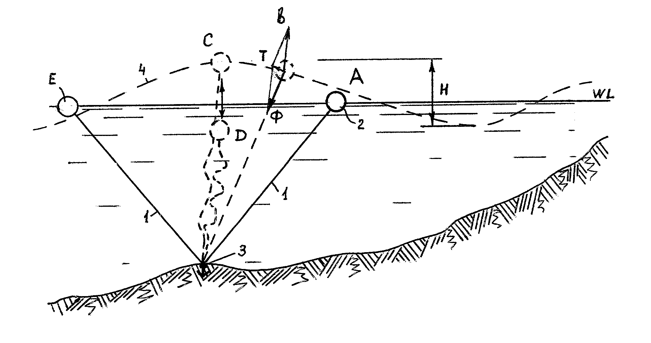
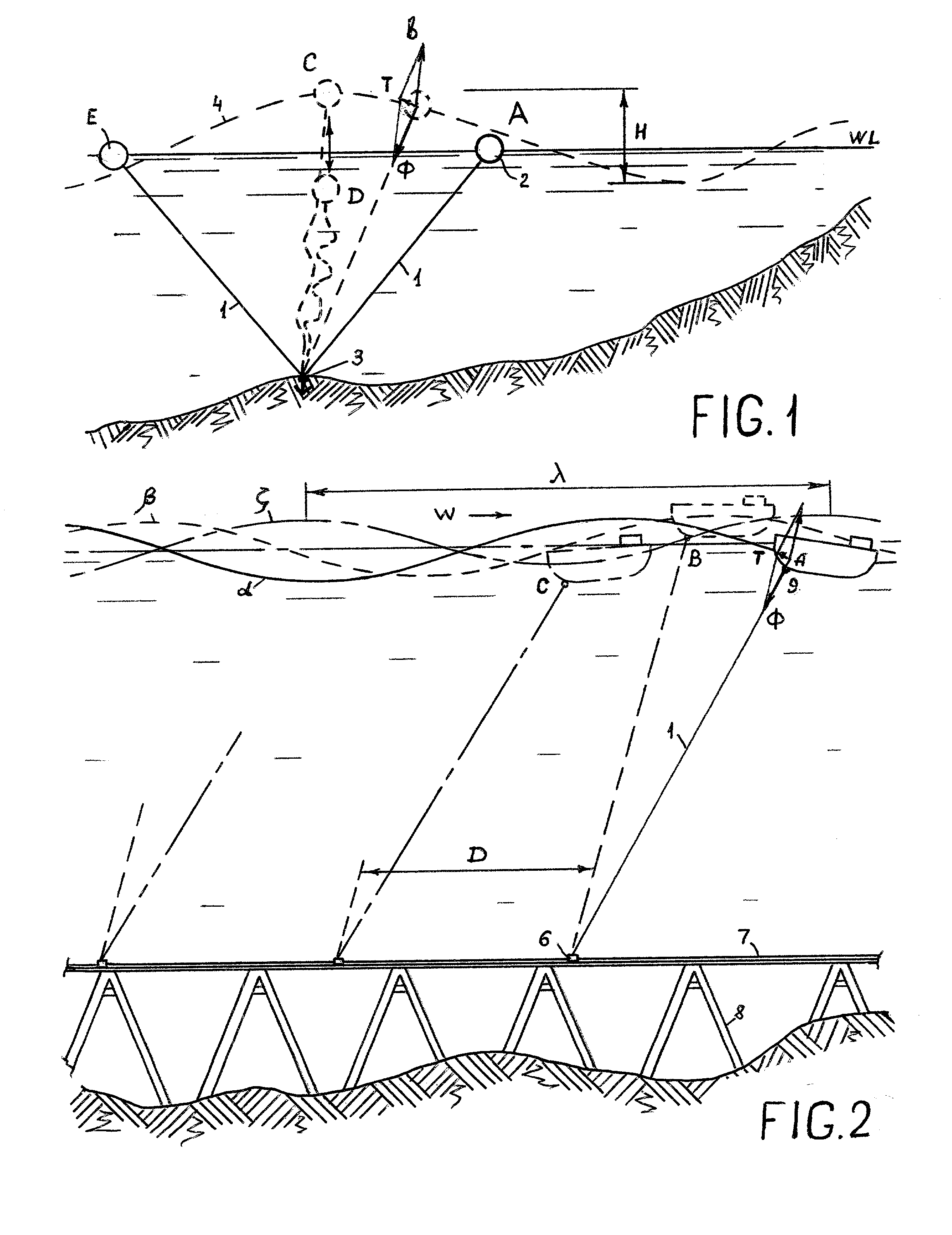
[0063] The method of the ship propulsion using the deep submerged anchoring propulsion system comes from observation of a buoy hard anchored near a coast. During calm water, a buoy 2 usually stays near a coastline (position A) held by anchor 3 through rope 1 as shown on the FIG. 1. In case a single wave come in, it tests two additional forces: pulling force, additional buoyancy force b. The vector sum of these forces is resulting force T directed perpendicular to the rope 1 and it is a thrust forcing the buoy to move against the water drag. The same phenomenon is happening if the buoy is located on the opposite side (position E). From any position a wave moves the buoy to the center C.

[0064] In case of recurring waves, the buoy saves its central state bobbing between points C and D. When it is located in the position D the rope 1 weakens. At this moment, the anchor 3 can mo...


PUM


Abstract

Method of cyclic anchoring itinerant (CAI) propulsion uses a phenomenon of anchored float horizontal motion as wave rises. The method repeats a cycle: Detaching the anchor from an immobile medium as a wave begins descent; Accelerating it in new position as the wave descends; Reattaching it to said medium as a wave rises. The medium can be railway or water. Respectively a trolley or a glider works as the anchor. To drag as anchor the glider orients perpendicular to the link. Improvements: adding an auxiliary propeller accelerating the glider, connecting bow and aft gliders with a single boom, making it telescopic, adding a small submarine hull for permanent observation water space, scientific researches, entertainment. The method allows to reequip watercrafts to all-weather, ocean going watercrafts with an unlimited range of operation. These solutions can be widely used in marine rescue remedies. Experimental models of CAI propulsion system show remarkable results.

Description

[0001] Wave powered ship propulsion systems have an extensive history of inventions. However, prior attempts at invention have not, as yet, been successfully implemented. All of these designs are tightly attached to a ship body. Some of which use ship rocking to be driven (U.S. Pat. No. 6,099,368). There are no propulsion systems, which are wave powered and dangled in deep water to work.[0002] This invention presents a new method of ship propulsion having no analogs. It is based on well-known phenomenon of surface movement of anchored buoys or other floats caused by the ocean or tidal action. This invention supposes to use as anchors special devices named here by cyclic anchoring itinerant (CAI) devices that shift forward to a new remote position with the next wave. Powered by wave these devices and methods of ship propulsion can play a significant original role in Merchant Marine, Navy, Research and Fishing fleets, Marine rescue remedies, entertainment, and sports.STATEMENT REGARDI...

Claims


Application Information

Patent Timeline
IPC IPC(8): B63H19/02
CPCY02T70/59B63H19/02Y02T70/5236
Inventor GORSHKOV, VLADISLAV VASILYEVICH
Owner GORSHKOV VLADISLAV VASILYEVICH
Learn More