
Automobile drip molding, mounting construction thereof and method of mounting

a technology for drip molding and automobiles, applied in mechanical devices, roofs, transportation and packaging, etc., can solve the problems of affecting the appearance of external objects, affecting the sealing properties of sealing lips, and affecting the lateral field of view of drivers

Inactive Publication Date: 2003-11-27
HONDA MOTOR CO LTD +1
View PDF2 Cites 4 Cited by
  • Summary
  • Abstract
  • Description
  • Claims
  • Application Information

AI Technical Summary

Problems solved by technology

However, with conventional drip moldings, there were the following problems in achieving the desired object of preventing water from overflowing (water-damming action).
I. Problems Regarding the Sealing Properties of the Sealing Lip Section
However, this divided type of construction suffered from the difficulty that external appearance was adversely affected by the appearance of a joining portion of the two members.
That is, conventionally, the water-damming action is poor, leading to the problem of obstruction of the lateral field of view of the driver.
However, with this conventional molding mounting construction in which the direction of attachment of the molding was the same at all locations (downwards from above), if, during use, upwardly directed external force caused the molding to become detached at one location, the external force could propagate to other portions, resulting in the molding easily becoming detached over a wide range (in the worst case, the entire molding), giving rise to the problem that the principal function of the molding to prevent the water invasion can no longer be achieved.
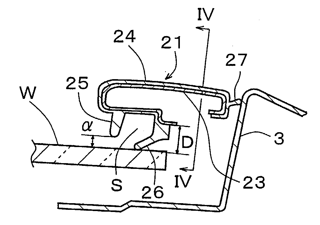
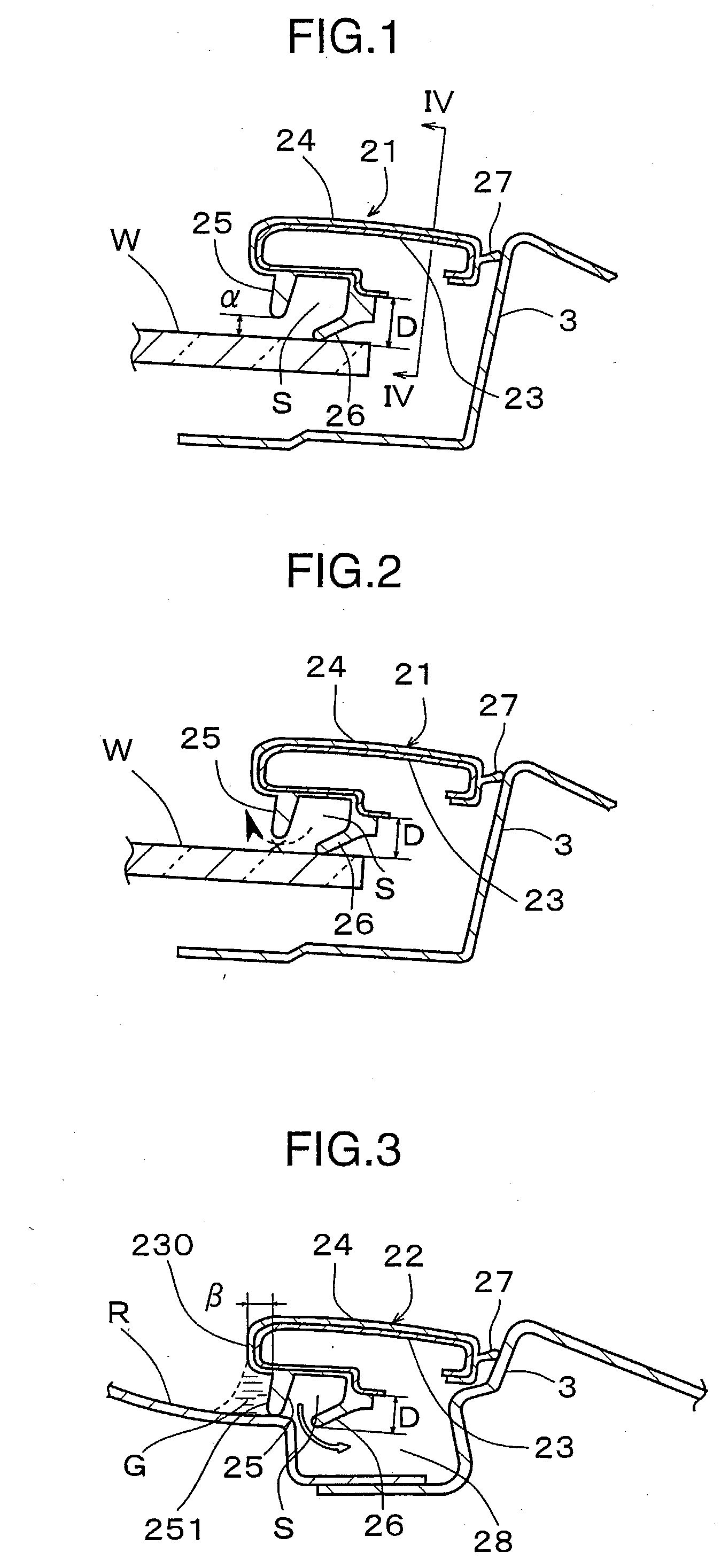
However, in this first embodiment, since the second lip section 27 is formed as a simple club-shaped tongue so that the leading end of this lip section 27 only makes line contact with the flat upright surface of the side panel 3, the contact stability of this lip section 27 is low with the result that noise is generated by severe minute vibrations of this lip section 27 produced by wind pressure during running.
Also, since the leading end of this lip section and the surface of the side panel rub against each other due to this vibration of the second lip section 27, there is a risk of the portion that contacts the side panel 3 being damaged in protracted use, or of deformation of this section 27, leading to impaired sealing thereof.

Method used


Image

  • Automobile drip molding, mounting construction thereof and method of mounting
  • Automobile drip molding, mounting construction thereof and method of mounting
  • Automobile drip molding, mounting construction thereof and method of mounting

Examples


Embodiment Construction

[0115] (1) Although, in the second embodiment described above, the procedure was adopted of attaching the molding in the sequence: rear end of the roof guard section 22other portions of this section 22portions of the window guard section 21 other than the front end thereoffront end of this section i.e. of attaching from the rear to the front, would be possible to adopt the reverse procedure of attaching from the front to the rear, or to adopt the procedure of attaching both the front and rear ends after attaching the intermediate section of the molding.

[0116] However, as a result of trial and error by the inventors, it has been established that greatest ease of operation is achieved if the molding is mounted with the attachment procedure and directionality of the embodiments described above.

[0117] (2) Instead of the second embodiment described above, it would be possible to make only the direction of attachment of the window guard section 21 and roof guard section 22 different, or t...


PUM


Abstract

In an integral drip molding in which a window guard section 21 along the front window W and a roof guard section 22 along the roof R are integrally formed, a lip section that contacts the front window W or the roof R is of a double construction, having an outer lip section 25 and inner lip section 26. The inner lip section 26 in the roof guard section 22 is positioned within a concave groove 28 formed at the portion where the roof R and the side panel 3 are connected, so that water that is forced into the rear section of the window guard section 21 flows into the concave groove 28 through a space S between the two lip sections 25 and 26. Thus overflow of water from the rear end of the window guard section to the side window is reliably prevented.

Description

[0001] 1. Field of the Invention[0002] The present invention relates to an automobile drip molding for preventing rainwater flowing from the front window (windshield) or roof towards the side window during running and interfering with the lateral field of view of the driver.[0003] 2. Description of the Related Art[0004] As shown in FIG. 11, a drip molding comprises a window guard section 1 and a roof guard section 2, the window guard section 1 being mounted in the region where the vehicle body side panel 3 joins the front window W and the roof guard section 2 being mounted in the region where the side panel 3 joins the roof R, respectively, so as to prevent water from flowing out from the regions of these two junctions towards the side window and thereby safeguard the lateral field of view of the driver.[0005] It should be noted that the window guard section 1 and the roof guard section 2 could be integrally formed in a linked fashion or could be separately formed and linked by a jo...

Claims


Application Information

Patent Timeline
Patent Type & Authority Applications(United States)
IPC IPC(8): B60J10/00B60J10/02
CPCB60J10/0045B60J10/0051B60J10/02B60J10/0088B60J10/0062B60J10/25B60J10/265B60J10/30B60J10/45B60J10/70
Inventor KAGAWA, MAMORUSASE, HIROYUKITAMURA, TETUJI
Owner HONDA MOTOR CO LTD
Learn More