
Seal for rolling bearing used in a wind turbine

a technology for wind turbines and seals, which is applied in the direction of mechanical equipment, rotary machine parts, engine components, etc., can solve the problems of excessive grease being ejected from the bearing, affecting the mounting time and cost, and achieving the effects of preventing moisture ingress, preventing grease from escaping, and being convenient to install

Active Publication Date: 2014-01-23
AB SKF
View PDF4 Cites 1 Cited by
  • Summary
  • Abstract
  • Description
  • Claims
  • Application Information

AI Technical Summary

Benefits of technology

[0010]It is a particular object of the present invention to provide a rolling bearing having at least a seal which is easy to install, which prevents grease from escaping from the bearing, even under the effect of a raised pressure inside the bearing, and which also prevents the ingress of moisture, dust and other bodies.
[0011]A further object to the present invention is to provide a rolling bearing having good wear and aging resistances.

Problems solved by technology

Thus, there is a risk that the surplus grease will be ejected from the bearing at the location of the seals.
However, the sealing arrangement disclosed in this document has the drawback of being force fitted into a groove formed on the inner ring of the rolling bearing in order to obtain its retaining on the ring.
This is detrimental in terms of mounting time and of cost.

Method used


Image

  • Seal for rolling bearing used in a wind turbine
  • Seal for rolling bearing used in a wind turbine
  • Seal for rolling bearing used in a wind turbine

Examples


Embodiment Construction

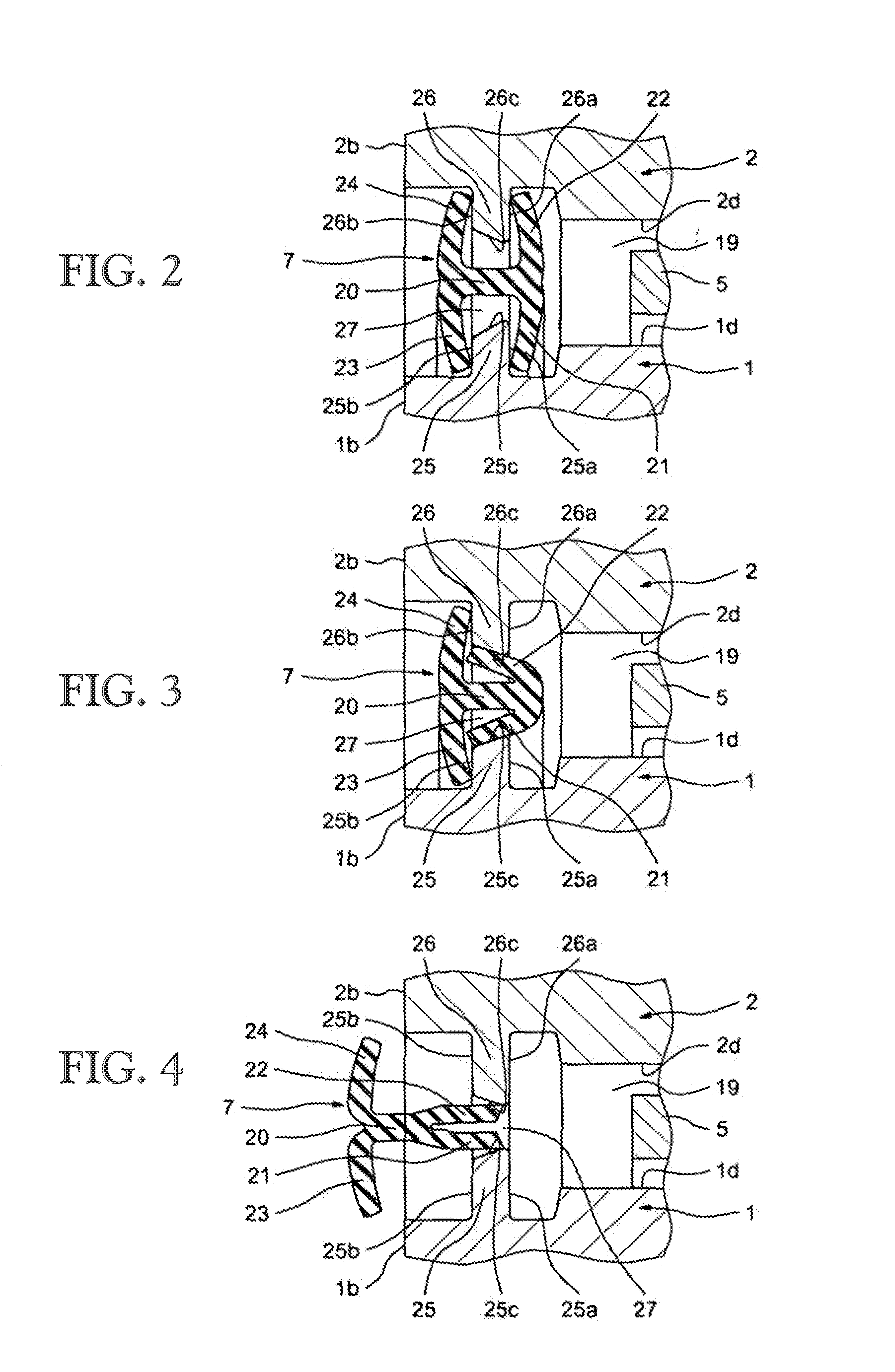
[0035]The rolling bearing as illustrated by FIG. 1 is a large-diameter rolling bearing comprising an inner ring 1 and an outer ring 2 between which are housed two rows of rolling elements 3 and 4, which in this case are balls, two annular cages 5, 6 for respectively maintaining the circumferential spacing of rolling elements 3 and 4, and two annular seals 7 and 8.

[0036]The inner and outer rings 1, 2 are concentric and symmetric with respect to a transverse radial plane passing through the centre of the rolling bearing. The inner ring 1 is of the solid type. A “solid ring” is to be understood as a ring obtained by machining with removal of material (by machining, grinding) from steel tube stock, bar stock, rough forgings and / or rolled blanks.

[0037]The inner ring 1 has a bore 1a of cylindrical shape designed to be fixed to a chassis or to a structure of a machine (not shown) and delimited by opposite radial lateral surfaces 1b, 1c. The inner ring 1 also includes a stepped exterior cyl...


PUM

PropertyMeasurementUnit
pressureaaaaaaaaaa
angleaaaaaaaaaa
thicknessaaaaaaaaaa

Abstract

The rolling bearing comprises an inner ring 1, an outer ring 2, at least one row of rolling elements and at least one seal 7 provided between the outer and inner rings. The seal 7 has, in cross section, the overall shape of an H and comprises internal lips 21, 22 and external lips 23, 24 forming the two substantially parallel branches of the H. The inner and outer rings 1, 2 comprise opposite radial ribs 25, 26 located axially between the internal and external lips 21 to 24 to axially retain the seal.

Description

CROSS-REFERENCE TO RELATED APPLICATION[0001]This application is a U.S. Non-Provisional Divisional Patent Application claiming the benefit of U.S. Non-Provisional Utility Patent Application Ser. No. 13 / 123,962 filed on 28 Jun. 2011, which is a National Stage Patent Application claiming the benefit of International Application Serial Number PCT / EP2009 / 63222 filed on 9 Oct. 2009, which claims the benefit of European Patent Application Serial Number PCT / EP2008 / 063793 having a priority date of 14 Oct. 2008, which are incorporated herein in their entireties.TECHNICAL FIELD[0002]The present invention relates to the field of seals used in the rolling bearings, and more particularly in the rolling bearings operating in an aggressive outdoor environment due to the presence of various kinds of pollution, such as splashing water, dust and other foreign matter, to the exposition of the ultraviolet radiation emitted by the sun, and to the variations of temperature.BACKGROUND ART[0003]This is nota...

Claims


Application Information

Patent Timeline
Patent Type & Authority Applications(United States)
IPC IPC(8): F16C33/76
CPCF16C33/767F16C19/181F16C2300/14F16J15/3236F16J15/3456F16J15/441F16C33/583F16C2360/31F16C33/7836F16C33/7816Y10T29/49679
Inventor GRUBER, ANDREASSWETE, WOLFGANGOVIZE, PASCALTANKE, JESKO-HENNINGFICK, AKE
Owner AB SKF
Learn More