
Pneumatic medical system

a medical system and pneumatic technology, applied in the field of pneumatic medical system, can solve the problems of inconvenient use, inconvenient use, and inability to effectively suction some materials, and achieve the effects of convenient assembly, manipulation, control, use and transportation, and easy manual holding and control

Inactive Publication Date: 2003-10-16
SCHULTZ JOSEPH P
View PDF24 Cites 10 Cited by
  • Summary
  • Abstract
  • Description
  • Claims
  • Application Information

AI Technical Summary

Benefits of technology

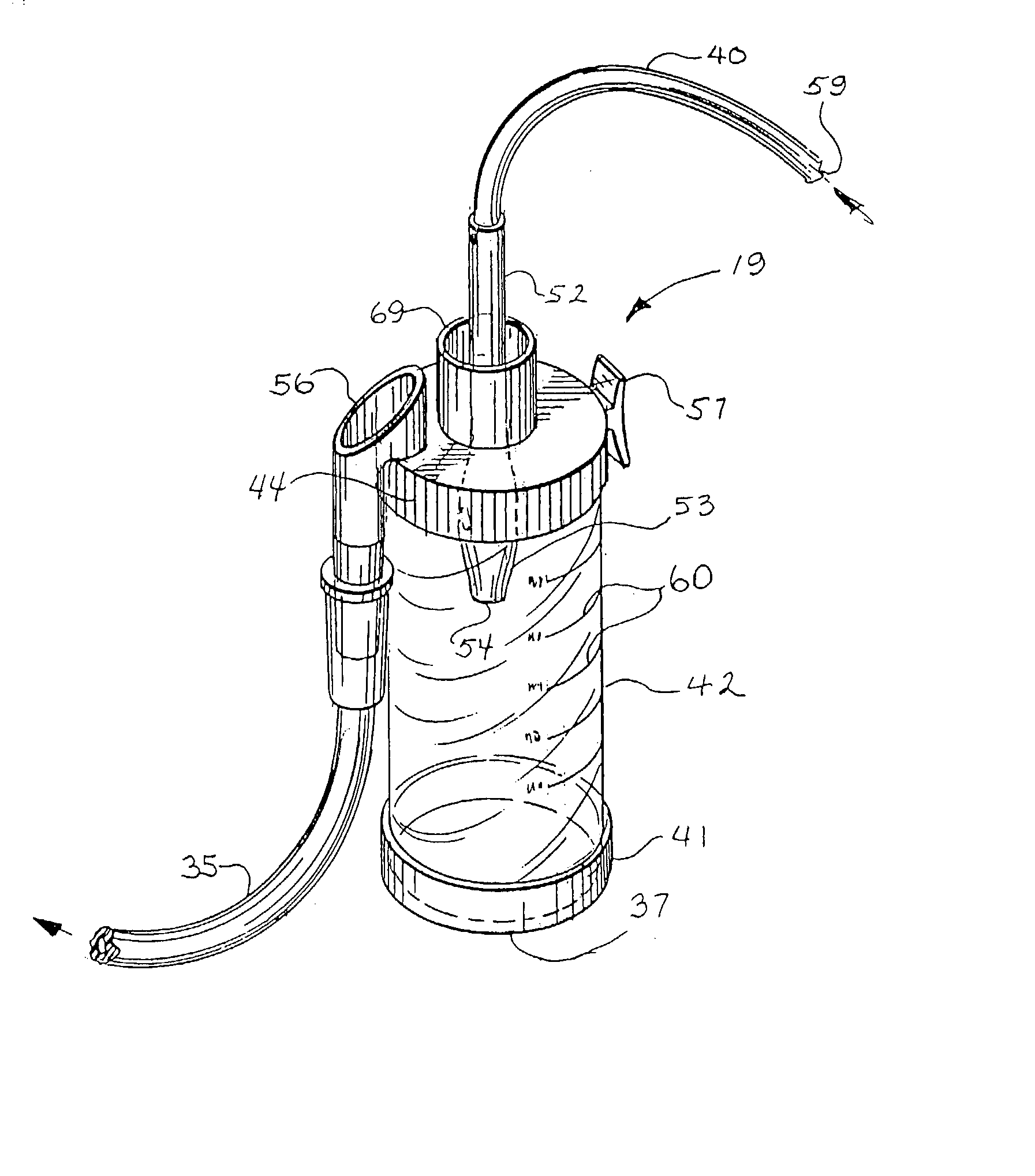
[0007] An object and feature of a preferred embodiment of the present invention is to fulfill the above-mentioned needs by providing a pneumatic medical system which is easy to assemble, manipulate, hold, manufacture, control, use and transport. It is also an object and feature of the preferred embodiment to provide a pneumatic system, including a vacuum aspiration system with specimen trap, that is made of fewer parts for easier manufacturing. In addition, it is an object and feature of the preferred embodiment to provide a pneumatic system, including a vacuum aspiration system with a specimen trap, that is oriented in such a way as to be easier to manually hold and control. It is also an object and feature of a preferred embodiment of this invention to provide a vacuum aspiration system which can collect fluids or other biological samples with a decreased incidence of clogging. In addition, it is an object and feature of a preferred embodiment of this invention to provide a system that is more easily cleared, should it become clogged.
[0008] It is also an object and feature of the present invention to provide a system of telescoping catheters to allow the physician more versatility in using different sizes of catheters, in connection with the suction device, or separately from it.
[0009] It is also an object and feature of this invention to provide a pneumatic medical system which can assist in the rapid administration of fluids to a patient with the use of a pressurized fluid source. It is also an object and feature of this invention to provide a pneumatic medical system that can assist in the rapid administration of fluids for irrigation purposes that may include wound irrigation with or without a splash shield. It is also an object and feature of this invention to provide a pneumatic medical system which can assist in the rapid administration of fluids to a patient with the use of an externally pressurized fluid source, which attaches to a readily available fluid reservoir, such as a bottle of sterile fluid.
[0010] It is also an object and feature of this invention to provide a pneumatic medical system which can assist in the rapid administration of fluids to a patient with the use of a pressurized fluid source, which may be continuous, or may be regulated, or may be continuously regulated. It is also an object and feature of this invention to provide a pneumatic medical system which can assist in the rapid administration of fluids to a patient with the use of a pressurized fluid source, which may be continuous, or may be regulated, or may be continuously regulated; which may be sterile or may be manufactured at a low cost, and may be disposable; which may attach to a common and readily available fluid source, such as a container of sterile fluid, such as a bottle of sterile saline; or which may have an outlet port of a fluid reservoir at or near the bottom of the reservoir, and which may have conduits or adaptors to mate with commonly available pressurized fluid sources or regulated pressurized fluid sources in medical settings, such as hospitals, which may include adaptors to connect with oxygen sources, such as oxygen tanks or oxygen regulators connected to oxygen tanks or wall sources; or which can assist in the rapid administration of fluids to a patient with the use of a pressurized fluid source, which may have a means to vary the diameter of the outflow conduit to vary the pressure of the fluid effluent, and may be adapted on the outlet end to mate with a wound irrigation shield to contain the pressurized effluent; or which can be rapidly or simply modified from a pneumatic system under positive pressure to rapidly and controllably administer fluid to a pneumatic system under negative pressure for use in containing suctioned specimens with a trap; and this might be accomplished by distraction or repositioning of an outflow tube to simplify stocking and promote recycling in medical settings.
[0011] It is also an object and feature of this invention to provide a multi-purpose pneumatic medical system that could be rapidly changed from catheters of varying dimensions for various functions, that might be constructed of telescopic or fixed tubing with a minimal amount of parts or assembly required.
[0012] It is a further object and feature of the present invention to provide such a system that is pre-filled with an irrigation fluid and is economical as a single use device.

Problems solved by technology

Bulb syringes are easy to use, but have limited capacity.
However, they might not be of the correct length, suction strength, or size to effectively suction some material.
Suction catheters may be difficult to control.
For example, a long thin catheter may bend or kink, decreasing its ability to perform suction.
It may also be difficult to control the power of the suction using a suction catheter.
This volume of fluid may be predictive of a poor outcome for the baby.
DeLee traps can become clogged.
As the canister fills with specimen fluid, the inlet tube may become blocked, leaving the inlet tube with a volume space that may be difficult for the vacuum to overcome.
Once clogged, it can be very difficult to clear a clog and reactivate the device.
DeLee traps can also be very awkward to use.
This cumbersome arrangement is poorly suited to procedures that demand the physician and assisting medical support teams quickly transition between tasks.
The example of suctioning a newborn is just one of many instances in which specimen traps are cumbersome to use during important medical procedures.

Method used


Image

  • Pneumatic medical system
  • Pneumatic medical system
  • Pneumatic medical system

Examples


Embodiment Construction

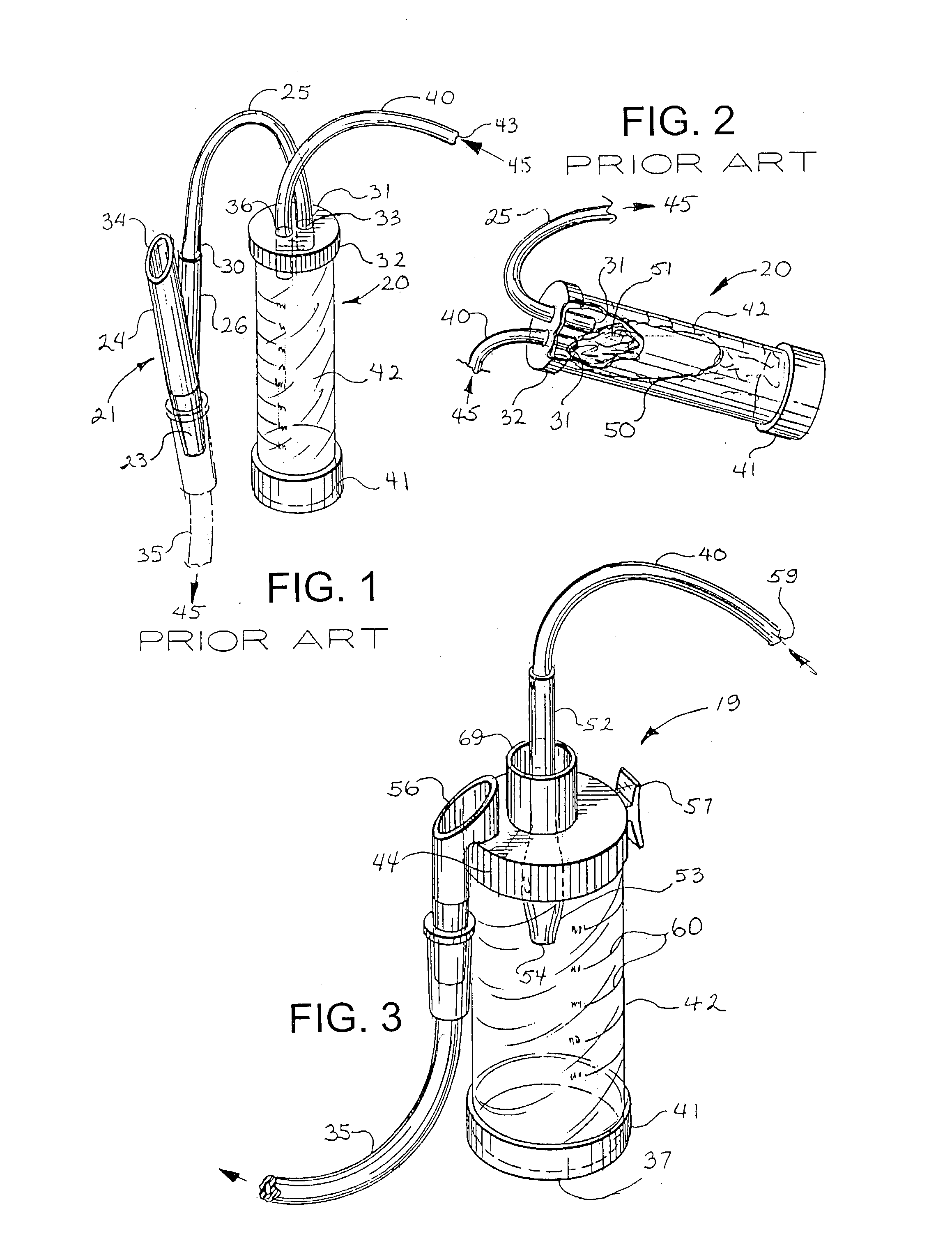
[0040] FIG. 1 illustrates the prior art. Shown in FIG. 1 is a specimen trap, also called a DeLee trap or DeLee trap system 20. Illustrated in FIG. 1 is outlet catheter 35. Outlet catheter 35 is attached at its distal end to a well-known vacuum source, such as a wall-mounted adapter, well known in the art (not shown). Outlet catheter 35 is attached at its proximal end to the cylindrical hollow bottom end 23 of the Y-shaped thumb valve 21. At the opposite end from bottom end 23 of Y-shaped thumb valve 21 are two cylindrical hollow tubes, a valve tube 24 and a catheter tube 26. Valve tube 24 and catheter tube 26 fuse to form cylindrical hollow bottom end 23 (as shown). Outlet catheter 25 has a distal connection end 30 and a proximal canister cap end 31 (as shown). Connection end 30 of outlet catheter 25 is connected to catheter tube 26. Canister cap end 31 of outlet catheter 25 passes through canister cap 32 through hole 33. Valve tube 24 has a diagonal top end 34. Also attached to can...


PUM


Abstract

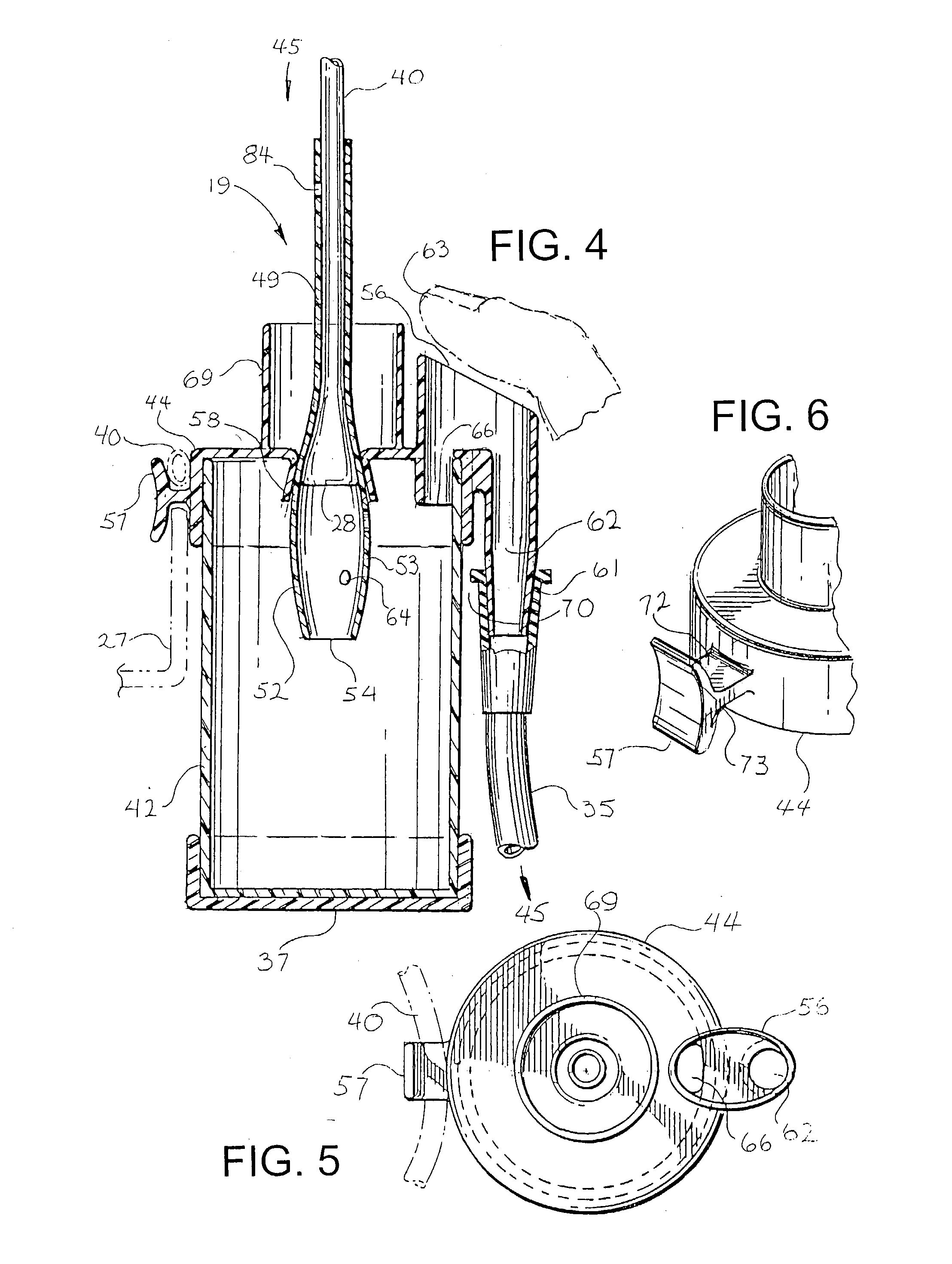
A pneumatic medical system, which includes a collection canister with a lid. Integrally attached to the lid are inlet and outlet ports, a thumb valve to regulate the level of suction or pressure in the system, a clip to hold a loop of catheter, an endotracheal tube adaptor, and a single hole for a single-suction catheter. The suction catheter has telescoping lengths and sizes of catheter attached so that the user can increase the diameter of catheter to be used by removing smaller diameter catheters. A smaller diameter catheter can be removed by pulling the smaller diameter catheter through the telescoping nested attachment with the larger diameter catheter. If the canister becomes full or clogged, it can be easily cleared by tipping the canister and pouring the contents through the thumb valve. The system requires only one hand and is easy to hold and manipulate. A disposable and pre-filled irrigation system is also disclosed.

Description

[0001] The present application is a continuation-in-part of related Utility application Ser. No. 10 / 067,459, filed Feb. 4, 2002, entitled "PNEUMATIC MEDICAL SYSTEM", and Applicant's prior U.S. Provisional Application Serial No. 60 / 266,110, filed Feb. 2, 2001, entitled "PNEUMATIC MEDICAL SYSTEM", the contents of which are herein incorporated by reference and are not admitted to be prior art with respect to the present invention by its mention in this cross-reference section.[0002] Pneumatic systems have a variety of uses in medical settings. Newborn babies are sometimes "suctioned" when they are born. Suction devices, such as bulb syringes, suction catheters or DeLee traps, are used to remove fluid, meconium and other secretions from the baby's mouth, nose, lungs and stomach. Suction devices can be attached to sterile canisters for collecting specimens from suctioned material for later laboratory analysis. This is used on both pediatric and adult patients. Sometimes the traps are use...

Claims


Application Information

Patent Timeline
Patent Type & Authority Applications(United States)
IPC IPC(8): A61M1/00A61M3/02
CPCA61M3/0237A61M1/0047A61M3/025A61M3/0208A61M3/0216A61M1/7411A61M1/772A61M1/60
Inventor SCHULTZ, JOSEPH P.
Owner SCHULTZ JOSEPH P
Learn More