
Systems and methods for measuring pulse wave velocity and augmentation index

a technology of pulse wave velocity and augmentation index, which is applied in the field of noninvasively measuring vascular pressure waveforms, can solve the problems of inability to accurately measure the vascular pressure waveform prior to noninvasive blood pressure waveform measurement techniques, the risk of bleeding, and the possibility of infection

Inactive Publication Date: 2003-08-28
COLIN
View PDF4 Cites 17 Cited by
  • Summary
  • Abstract
  • Description
  • Claims
  • Application Information

AI Technical Summary

Benefits of technology

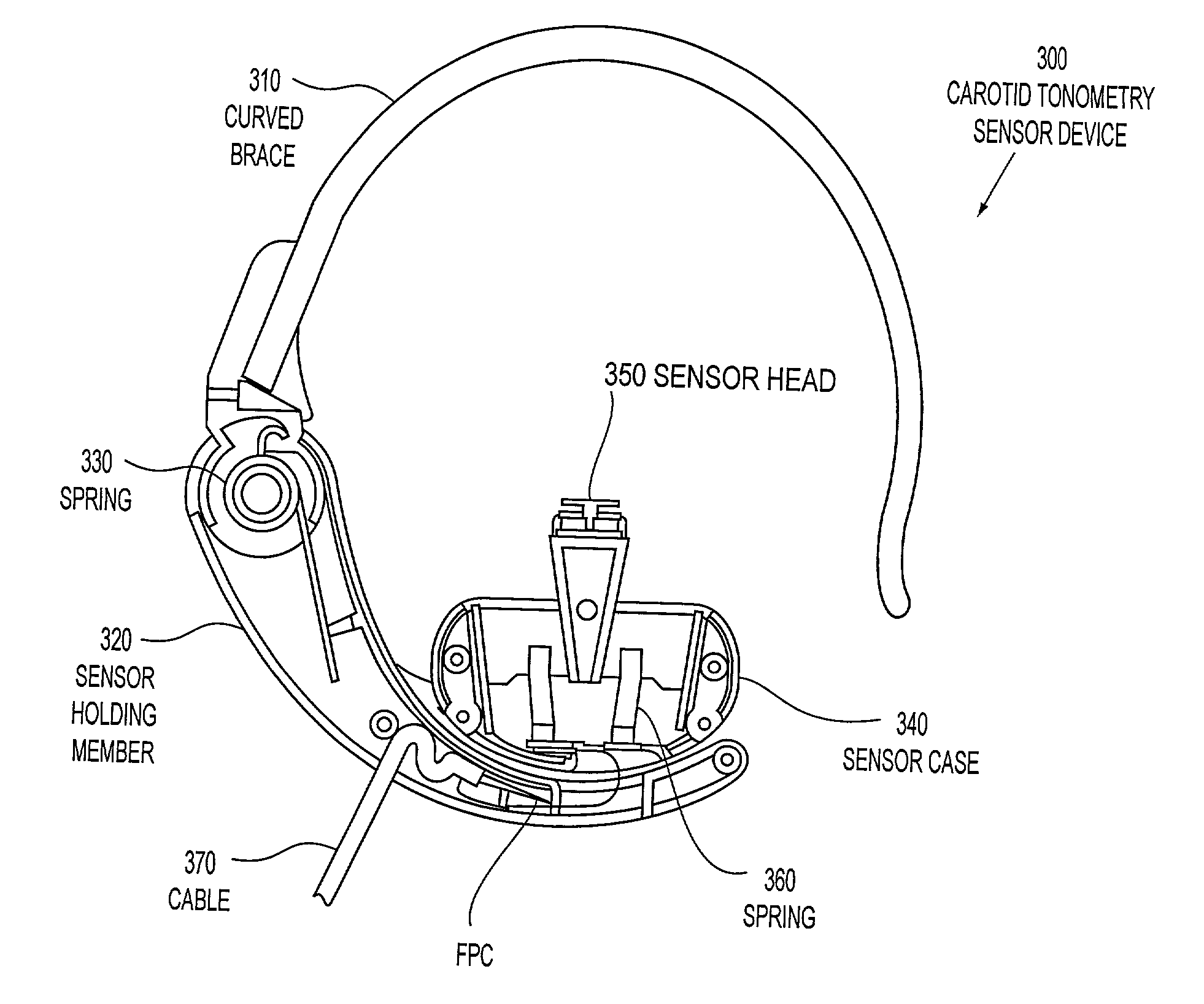
[0019] Various exemplary embodiments of the systems and methods according to this invention include a device that reliably produces a graphical representation of an arterial pressure waveform by controlling the damping conditions of the sensor applied to the carotid artery. Damping the sensor reduces, or, ideally, eliminates, distortions in the measured pressure waveform, such that the data derived from the measured pressure waveform may be meaningfully compared to generally accepted values, for example, for the pulse wave velocity and / or the augmentation index for a healthy living being. Such a comparison requires that the measured waveform have substantially the same shape as a hypothetical perfectly-sensed pressure waveform from which the generally accepted values would be derived.
[0023] Various exemplary embodiments of the vascular tonometry sensor according to this invention include a substantially C-shaped device that fits around a living being's neck. Thus, aligning the sensors against that living being's neck in the area or location of, for example, the carotid artery, is very easily achieved. As a result, the vascular pressure waveform in the carotid artery is accurately sensed without needing to tediously align and re-align the device. This reduces the expertise and experience level required to use such exemplary embodiments of the vascular tonometer sensor according to this invention, while still being able to reliably sense the arterial pressure waveform.

Problems solved by technology

Because prior noninvasive blood pressure waveform measurement techniques have proven inaccurate, pulse wave velocity is most commonly measured, for example, by inserting catheters into the vascular system at two distinct locations of an artery.
However, inserting of catheters into the body invites the danger of bleeding, as well as the possibility of infection.
Therefore, using such catheters to measure pulse wave velocity is not a preferred method of screening for arteriosclerosis or other aging of the vascular system in a living being.
The same arterial tonometry system or technique is not feasible, at least with a high degree of reliable accuracy, for measuring a pressure waveform in, for example, a carotid artery in a living being's neck.
In particular, the tissues of the neck preclude such a tonometer sensor from adequately compressing the carotid artery to yield an accurate pressure waveform as is possible in the radial artery measurement technique.
Such a pencil-type tonometer is not readily usable since it requires considerable expertise and experience in order to obtain a high-fidelity carotid pressure waveform of reliable accuracy.
Moreover, motion artifacts can easily, and detrimentally, affect the fidelity of a pressure waveform in a pencil-type tonometer.
In addition, the pencil-type tonometer is susceptible to inadvertent motions of a person or of the pencil-type sensor.
Such inadvertent motions often render inaccurate the pressure waveform representations obtained from the pencil-type tonometer.
Any substantial distortion of the shape of a measured arterial pressure waveform from the shape of the hypothetical perfectly-sensed arterial pressure waveform would render comparing the two waveforms unreliable for predicting the existence, or likelihood, of vascular obstructions, disease, or other deficiencies in a living being's vascular system based on values derived from the two differently-shaped waveforms.

Method used


Image

  • Systems and methods for measuring pulse wave velocity and augmentation index
  • Systems and methods for measuring pulse wave velocity and augmentation index
  • Systems and methods for measuring pulse wave velocity and augmentation index

Examples


Embodiment Construction

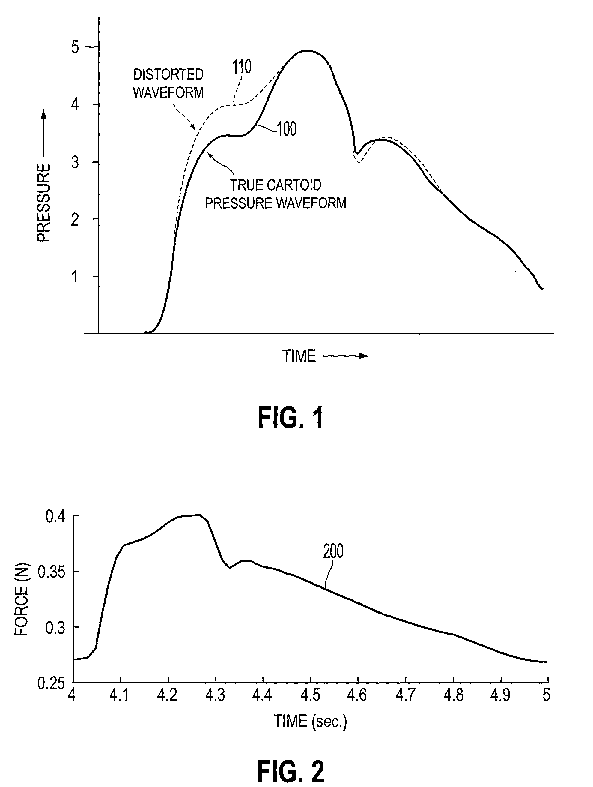
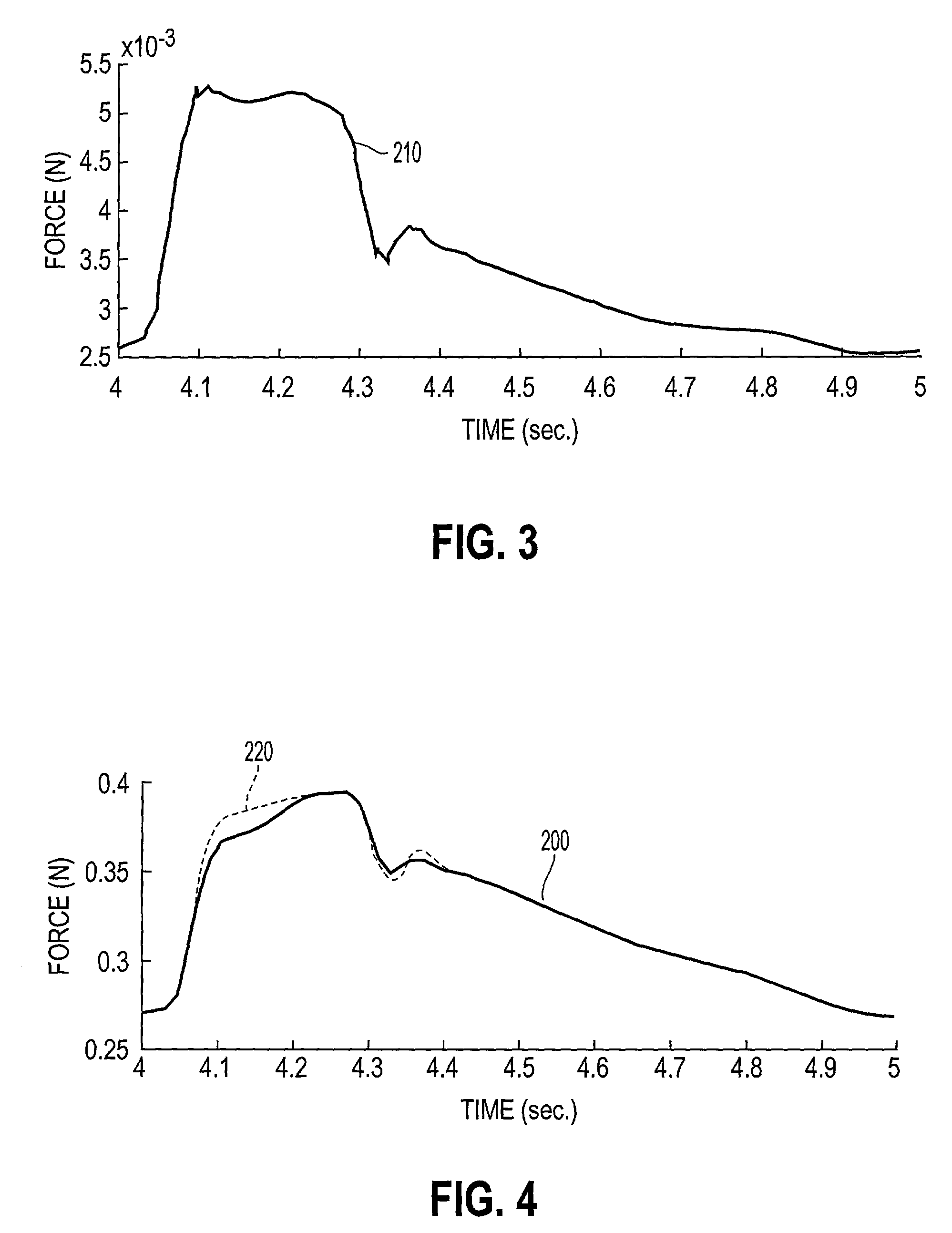
[0040] FIG. 1 illustrates a general representation of an exemplary hypothetical perfectly-sensed carotid artery pressure waveform 100 of a living being. The hypothetical perfectly-sensed carotid artery pressure waveform 100 is a representation of the shape one could expect a pressure waveform to have, were one able to have a sensor in the aorta to detect the initial and secondary thrusts of blood ejected from the heart or a sensor in the carotid artery, for example, to detect when the initial and secondary thrusts of blood from the heart have reached the carotid artery. The hypothetical perfectly-sensed carotid artery waveform 100 of any being is unique. The hypothetical perfectly-sensed carotid artery pressure waveform is related to several quantifiable factors, such as age, height, weight, and the like, as well as being based on many pertinent non-quantifiable factors, such as mental, emotional and psychological conditions.

[0041] FIG. 1 further illustrates a general representation...


PUM


Abstract

A noninvasive system and method of measuring vascular pressure waveforms in a living being includes a tonometric sensor device that reduces, or ideally, eliminates, distortion in the vascular pressure waveforms measured. The data from the vascular pressure waveforms are manipulated to determine cardiovascular conditions of a living being based on a comparison of measured augmentation index and / or pulse wave velocity values to typical values for healthy living beings of similar physiological characteristics.

Description

[0001] 1. Field of Invention[0002] This invention relates to non-invasively measuring a vascular pressure waveform.[0003] 2. Description of Related Art[0004] The pulse wave velocity, that is, the velocity at which a pressure wave propagates along a blood vessel, such as an artery, varies depending on the physical characteristics and properties of the blood vessel. Such properties may include the stiffness (elasticity) and geometrical dimensions of the vessel. Elastic properties of blood vessels are known to change with aging and with the onset and development of arteriosclerosis.[0005] Determining the pulse wave velocity depends on accurately measuring pressure waveforms at two distinct locations on the body. The wave propagation time is then derived by determining the time it takes the pressure waveform to travel the distance (d) between the two distinct locations. The pulse wave velocity is then determined as the ratio of the distance (d) between the two distinct locations and the...

Claims


Application Information

Patent Timeline
IPC IPC(8): A61B5/02A61B5/0245A61B5/021A61B5/025A61B5/0285A61B5/352A61B7/04
CPCA61B5/021A61B5/02125A61B7/04A61B5/0456A61B5/6822A61B5/0285A61B5/352
Inventor ECKERLE, JOSEPH STEPHENMARLOW, JOHN
Owner COLIN
Learn More