Tube pump, ink jet recording device, and ink feeding method

a technology of ink jet and tube pump, which is applied in the direction of pump control, positive displacement liquid engine, printing, etc., can solve the problems of deteriorating printing quality, difficult to detect the remaining amount of ink, and lowering the jet performance of ink droplets, so as to prevent air from entering, eliminate the negative pressure inside the main tank, and simple mechanism and operation

Inactive Publication Date: 2010-08-10
SII PRINTEK +1
View PDF4 Cites 12 Cited by
  • Summary
  • Abstract
  • Description
  • Claims
  • Application Information

AI Technical Summary

Benefits of technology

[0012]A tube pump according to the present invention includes: a pump main body having a space portion defined therein, including: a circular arc-shaped guiding member formed on an inner circumference of the pump main body over a predetermined angle range; and an opening portion communicating with the space portion; a tube provided along the guiding member and led out from the opening portion; at least one pressing member rotationally driven around a shaft coaxial with the guiding member, for pressing the tube against the guiding member; driving means for controlling the rotational drive; and flow passage securing means provided to the guiding member to which the tube is provided. Accordingly, when the pump is stopped for replacing a main tank, negative pressure inside an ink supply passage and the main tank can be eliminated.
[0013]Further, in the tube pump of the present invention, the flow passage securing means is defined by at least one recessed portion of the guiding member, in which the tube is not pressed by the guiding member and the pressing member. Accordingly, during stoppage for replacing the main tank, the negative pressure inside the main tank can be eliminated with a simple mechanism and operation.
[0014]Further, in the tube pump of the present invention, the number of the pressing member is the same as the number of the recessed portion or larger than the number of the recessed portion by one. Accordingly, it is possible to reliably prevent air from entering the ink supply passage from atmosphere and to sufficiently exert pump efficiency required for supplying the ink.
[0015]Further, an ink jet recording device according to the present invention is an ink jet recording device for performing recording onto a recording medium by jetting ink from recording means, which includes a tube pump including: a pump main body having a space portion defined therein, including: a circular arc-shaped guiding member formed on an inner circumference of the pump main body over a predetermined angle range; and an opening portion communicating with the space portion; a tube inserted into the pump main body and provided along the guiding member and led out from the opening portion; at least one pressing member rotationally driven around a shaft coaxial with the guiding member, for pressing the tube against the guiding member; driving means for controlling the rotational drive; and flow passage securing means provided to the guiding member to which the tube is provided, to deliver the ink in an ink supply passage. Accordingly, it is possible to reliably prevent air from entering the ink supply passage from the atmosphere and to stably jet the ink from a nozzle of an ink jet recording head.
[0016]An ink supplying method according to the present invention includes: an ink remaining amount detecting step of detecting a state where an amount of ink sucked from a main tank to a sub-tank cannot satisfy a preferred amount even after a certain time period; a tube flow passage opening step of stopping, by position detection means for detecting a position of a pressing member and driving means for rotationally driving pressing means, the pressing member at a position where the pressing member opposes a recessed portion, and securing an ink flow passage inside the tube; and a tube closing step of stopping, by the position detection means and the driving means, the pressing member at a position where the pressing member opposes a portion of the guiding member other than the recessed portion, and closing the ink flow passage inside the tube. According to the method, when the main tank is replaced, it is impossible to eliminate the negative pressure inside the ink supply passage and effectively prevent air from entering.

Problems solved by technology

Therefore, in a case where air bubbles are included in the ink, the pressurized state of the ink becomes unstable and jet performance of the ink droplets is lowered, thereby deteriorating a printing quality.
However, the main tank 5 is made of a flexible bag, so it is difficult to detect the ink remaining amount.
Therefore, the main tank 5 may be replaced while still having a large amount of ink left, resulting in wasteful dumping of the ink.

Method used


Image

  • Tube pump, ink jet recording device, and ink feeding method
  • Tube pump, ink jet recording device, and ink feeding method
  • Tube pump, ink jet recording device, and ink feeding method

Examples


first embodiment

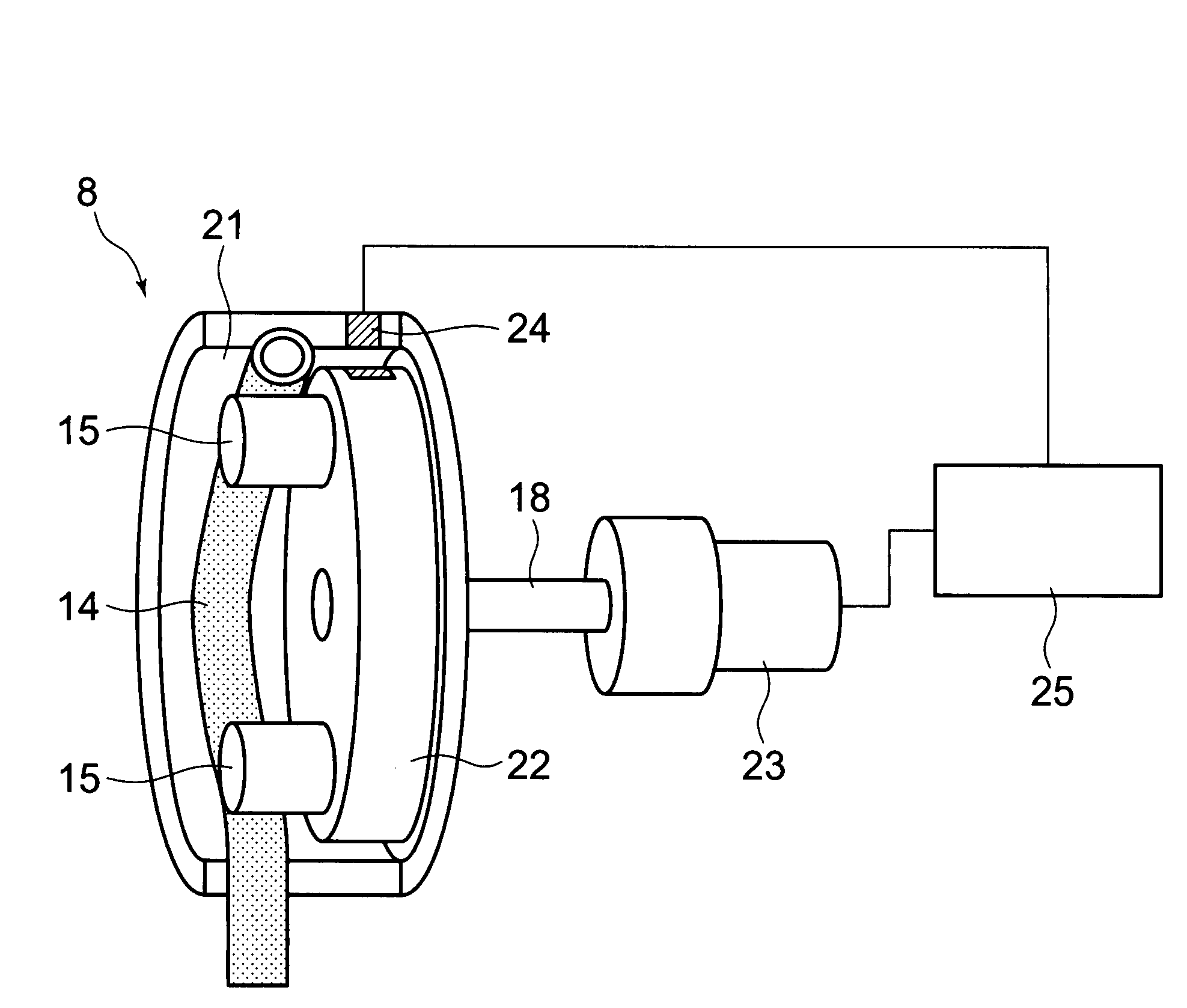
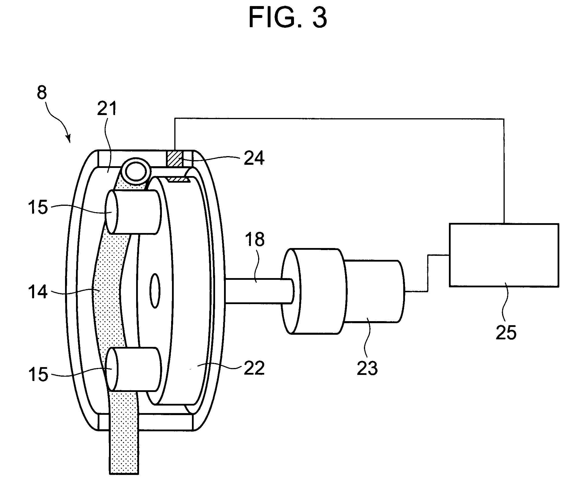
[0032]FIG. 2 is a sectional diagram schematically showing the tube pump 8 of the present invention for sucking ink in the main tank 5 to the sub-tank 9. Further, FIG. 3 is a diagram showing a control structure of the tube pump of the present invention. The tube pump of the present invention includes a pump main body 21 having a space portion defined therein, which includes a circular arc-shaped guiding member formed on an inner circumference of the pump main body 21 over a predetermined angle range and an opening portion that communicates with the space portion. Inside the space portion, there are arranged an elastic tube 14, a guiding member 16 which is a part of the pump main body, for guiding the tube 14 along the inner circumference, and rollers 15 serving as pressing members for pressing the tube 14 against the guiding member 16.

[0033]In the suction pump 8 of this embodiment, the above-mentioned predetermined angle is 180° or more, and the tube 14 is provided along the guiding ...

second embodiment

[0041]Next, the number of the rollers 15 to be used in the tube pump 8 of the present invention will be described. The number of rollers used in the tube pump of the present invention is at least one. However, in the case where there is one roller, even when a rotation number of the pump is increased, the pressure may not exceed a predetermined value, with the result that the ink cannot be sucked sufficiently from the main tank 5 to the sub-tank 9. In addition, when the pump is stopped and the ink flow passage is closed (locked) to stop the flow of the ink, an amount of pressured deformation cannot be secured due to a loosened shaft or the like, so a leak may occur. Thus, it is desirable that two or more rollers be used for the tube pump 8 of the present invention. Further, in a case where three or more rollers are provided, it is desirable that a plurality of recessed portion 17 be provided. As to the relation between the number of rollers and the number of the recessed portions, i...


PUM


Abstract

A tube pump includes: an elastic tube (14); a circular arc-shaped guiding member (16) for guiding the tube (14); and at least one pressing member (15) for pressing the tube (14) against the guide member (16). The tube pump is characterized by being provided with a recessed portion (17) in a portion of the guiding member (16), in which the tube (14) is not pressurized by the pressing member (15) and can be recessed. Thus, there can be provided a tube pump in which a negative pressure inside an ink supply passage (7) can be eliminated and air can be readily prevented from entering the ink supply passage (7) when the main tank (5) is replaced, and an ink jet recording device using the tube pump.

Description

CROSS-REFERENCE TO RELATED APPLICATIONS[0001]This application is a U.S. national stage application of International Application No. PCT / JP2005 / 018077, filed Sep. 30, 2005, claiming a priority date of Dec. 28, 2004, and published in a non-English language.TECHNICAL FIELD[0002]The present invention relates to a tube pump, and more particularly to a tube pump of an ink jet recording device for jetting ink droplets from a recording head to record an image onto a recording medium, which is used for supplying ink from a main tank serving as an ink supplying source to a sub-tank.BACKGROUND ART[0003]An ink jet recording device of a serial printing system as shown in FIG. 1 includes at least a delivery means for delivering a recording medium in a sub-scanning direction (not shown) and a recording head 1 which is mounted onto a carriage 2 and reciprocates in a main scanning direction orthogonal to the sub-scanning direction. The ink jet recording device has a structure for jetting ink droplet...

Claims


Application Information

Patent Timeline
Patent Type & Authority Patents(United States)
IPC IPC(8): F04B43/08F04B43/12F04B45/06
CPCB41J2/17596F04B43/1253B41J2/19
Inventor KUBOTA, YUZURUIWASE, FUMIYOSHI
Owner SII PRINTEK
Why Eureka
Try Eureka