
Self-drilling screw for use in steel houses

a self-drilling screw and steel house technology, applied in the direction of screws, threaded fasteners, fastening means, etc., can solve the problems of affecting the appearance of finished interiors, and the driver bit will probably come out of troubl

Inactive Publication Date: 2003-07-31
SHINJO MFG CO LTD
View PDF20 Cites 21 Cited by
  • Summary
  • Abstract
  • Description
  • Claims
  • Application Information

AI Technical Summary

Problems solved by technology

A portion of this plasterboard will contact the head 2a of such a bolt 2, and this head is prone to produce a protuberance in the surface of plasterboard 4, thereby impairing appearance of the finished interior.
If a motor-driven high-speed wrench or the like rotating at 2500 rpm or faster is used, then a very troublesome "caming-out" of its driver bit will probably happen.

Method used


Image

  • Self-drilling screw for use in steel houses
  • Self-drilling screw for use in steel houses
  • Self-drilling screw for use in steel houses

Examples


Embodiment Construction

[0018] Now some embodiments of the present invention will be described in detail, referring to the drawings.

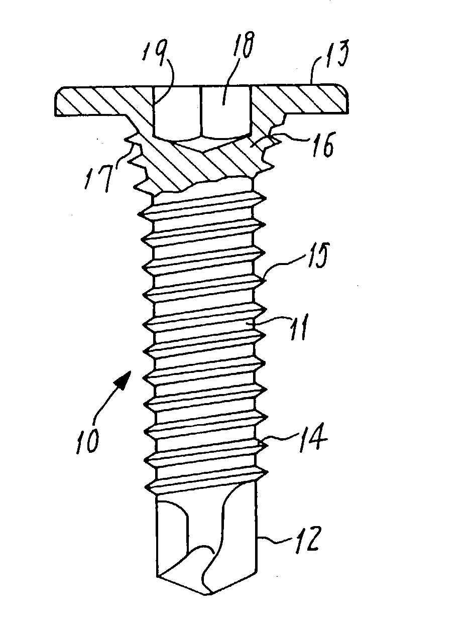
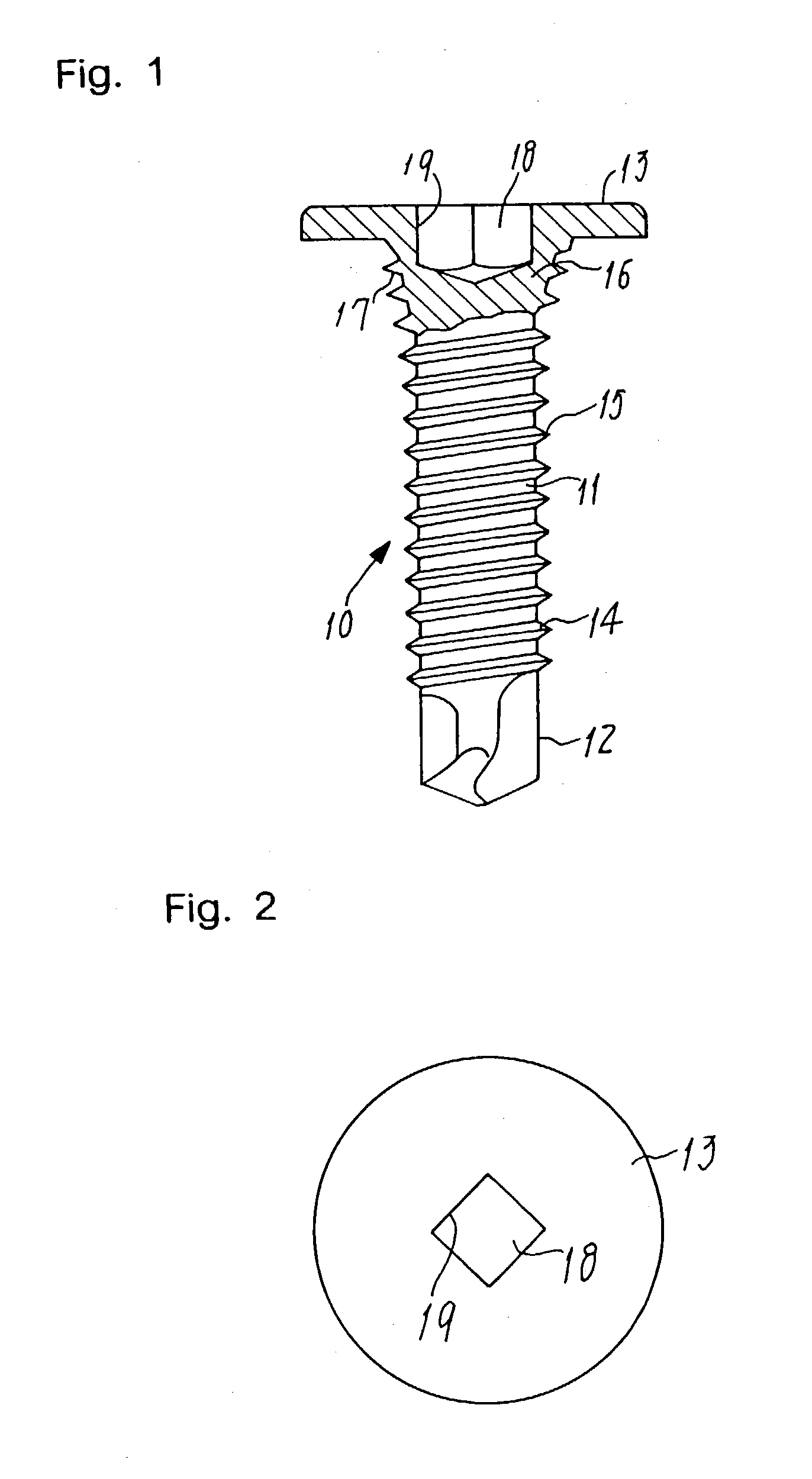
[0019] FIGS. 1 and 2 show a self-drilling screw 10 adapted for use in steel houses and provided in a first embodiment of the present invention.

[0020] This self-drilling screw 10 has a leg 11 with opposite ends, the one end being formed as a drilling portion 12. The other end is formed as a thinned flathead 13, so that a tapping thread 14 and a guiding thread 15 are formed around the leg 11. These threads extend between the flathead 13 and the drilling portion 12 so as to continue from the drilling portion 12. A neck 16 provided as a region of the leg 11 is made thicker in diameter than the remainder thereof and flared towards the flathead 13. A fastening thread 17 formed in and around the neck 16 continues from the guiding thread 15, but is made larger than it in diameter. On the other hand, a recess 18 formed in the flathead 13 for engagement with a driving tool is a square h...


PUM


Abstract

A self-drilling screw (10) for use in steel houses has a leg (11), one end of the leg being formed as a drilling portion (12), the other end continuing to a flathead (13) through a neck (16) disposed close to the flathead (13). A tapping thread (14) formed around the leg continue from drilling portion, with a guiding thread (15) continuing from the tapping thread. A fastening thread (17) formed around the neck has a larger diameter than tapping and guiding threads (14, 15), the neck (16) being a thickened portion of the leg (11). A recess (18) formed in flathead (13) to engage with a driving tool is defined by and between torque-receiving walls (19) extending in parallel with the screw axis and beyond a boundary between the flathead (13) and neck (16), so that a driver can fit in the recess of such a thinned flathead to transmit a strong torque to tighten the screw into a steel panel, without any fear of caming-out problem.

Description

[0001] The present invention relates to a self-drilling screw for use in steel houses, and more particularly relates to a self-drilling screw used to construct a steel frame employing C-beams, wherein these C-beams are zinc-plated steel plate articles having a relatively small thickness of about 1 mm and used in the so-called "two-by-four" system construction of houses.PRIOR ART[0002] Raw steel beams are combined with each other to form such a steel frame, generally using the so-called self-drilling screws. The shapes and dimensions of self-drilling screws are prescribed in the "KC Standards" (viz., standards established by the Japanese Official Society "Kozai Club") in Japan.[0003] Exemplified in FIG. 7 is a steel frame 1 constructed using a flathead bolt 2 qualifying as a screw defined in the KC Standards. A plasterboard 4 as a material for finishing the interior of a house may be attached to this frame 1. A portion of this plasterboard will contact the head 2a of such a bolt 2, a...

Claims


Application Information

Patent Timeline
Patent Type & Authority Applications(United States)
IPC IPC(8): F16B23/00F16B25/10F16B35/04
CPCF16B23/0038F16B25/0021F16B35/048F16B25/103F16B25/0057F16B23/00
Inventor SHINJO, KATSUMI
Owner SHINJO MFG CO LTD
Learn More