
Biochip including carbon nanotubes and method for sample separation using the same

a carbon nanotube and biochip technology, applied in the field of biochips, can solve the problems of difficult to achieve reliable data, apply pre-treatment technology, and difficult to make uniform spaces with nanometer size in the chip using these methods

Inactive Publication Date: 2003-06-26
SAMSUNG ELECTRONICS CO LTD
View PDF14 Cites 50 Cited by
  • Summary
  • Abstract
  • Description
  • Claims
  • Application Information

AI Technical Summary

Benefits of technology

[0010] Further, the present invention provides a method of separating or filtering a target substance from a sample containing various substances on a biochip to prevent sample contamination or experimental error.

Problems solved by technology

But, if an undesirable substance exists in a sample, it can be difficult to obtain reliable data.
But, there are still many problems in directly applying pre-treatment technology to a micro-channel or chamber of an LOC.
It is, however, difficult to make uniform spaces with nanometer size in a chip using these methods.

Method used


Image

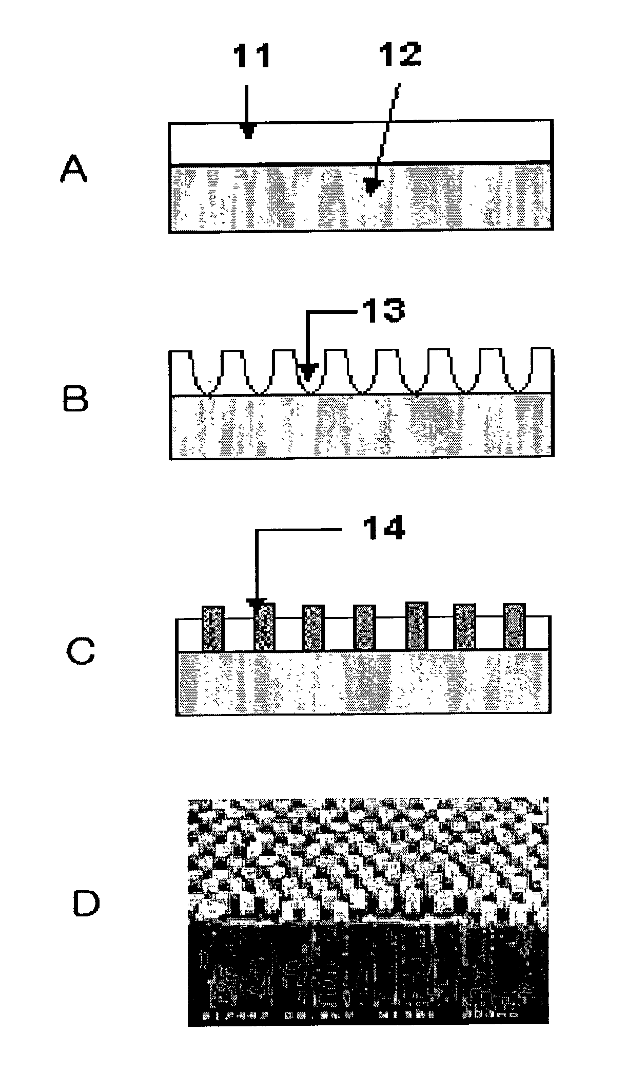
  • Biochip including carbon nanotubes and method for sample separation using the same
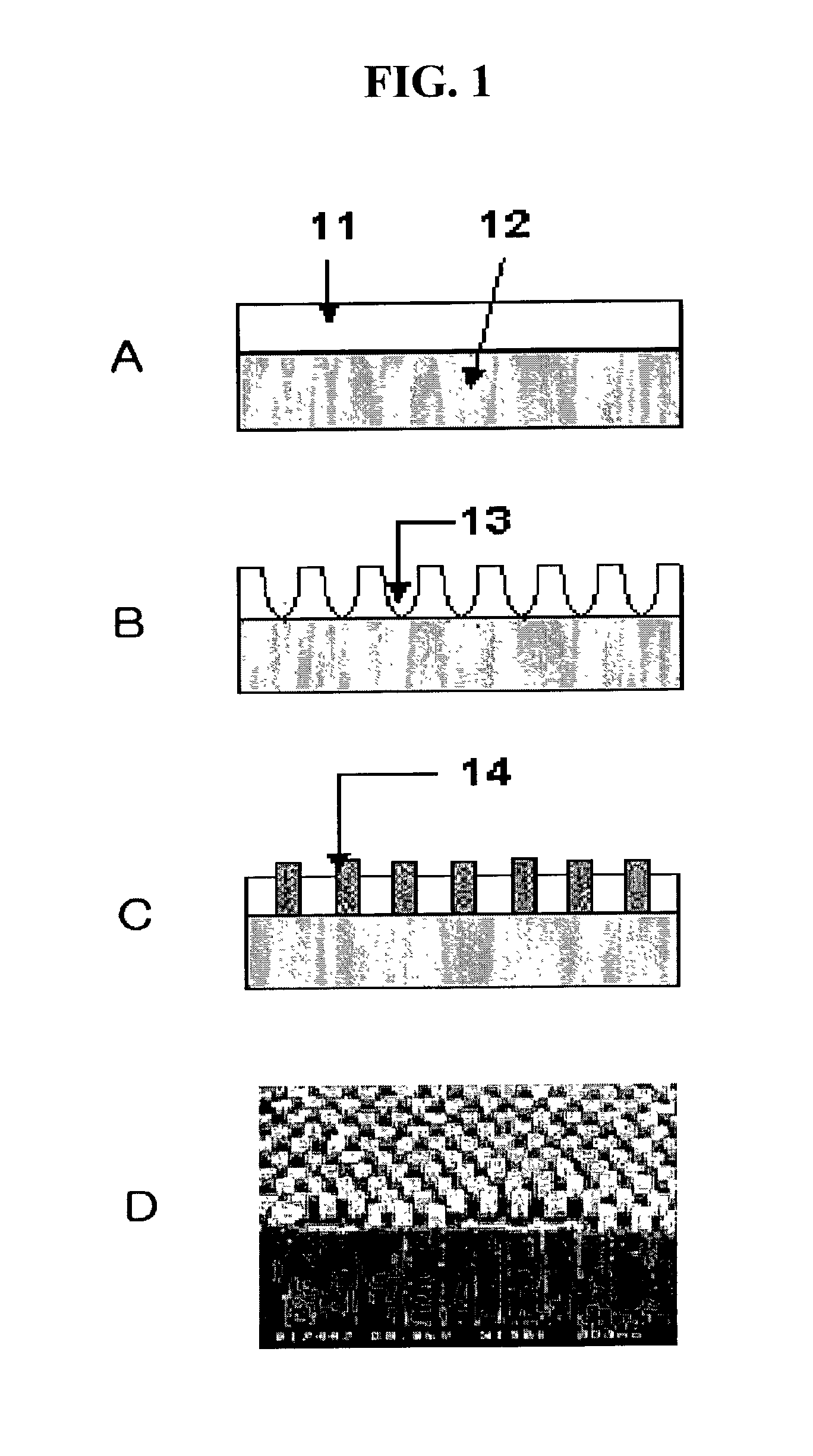
  • Biochip including carbon nanotubes and method for sample separation using the same
  • Biochip including carbon nanotubes and method for sample separation using the same

Examples


example 2

Separating or Filtering Biological Samples Using Carbon Nanotubes Inside the Channels

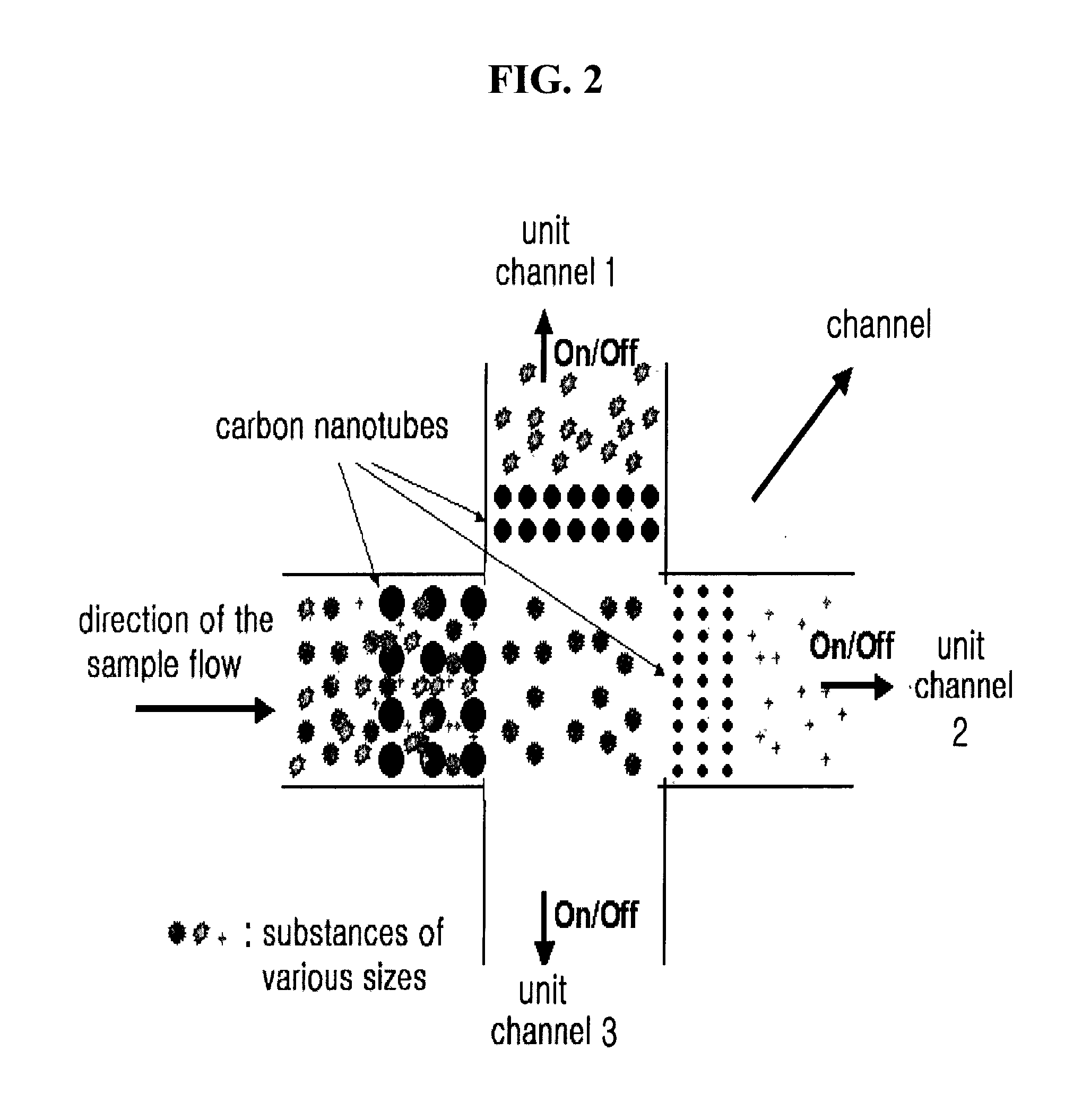
[0039] FIG. 2 illustrates one or more channels or chambers, each including a plurality of carbon nanotubes arrayed in various intervals. The channels or chambers can be used not only as a filtration device but also as a separation device. A force such as an electric field, a pressure, a vacuum, an electromagnetic field, and a centrifugation force may be applied to the channel so as to flow a fluid sample containing various substances.

[0040] For instance, a sample having a target substance and other various substances is disposed on the carbon nanotubes (which have different sizes and array patterns in each unit channel). Then, the sample may be moved in one direction by opening one or more unit channels extending in a sample flow direction and closing the remaining unit channel(s). Alternatively, a switch valve can be used to open and close the channels. By repeated opening and closing of the unit c...

example 3

Separation of White Blood Cells from Whole Blood

[0044] FIG. 4 shows a schematic diagram of a process for separating white blood cells from whole blood in the channels of a chip. The white blood cells can pass through the carbon nanotubes in a channel when the intervals between the carbon nanotubes are about 10 to about 20 micrometers. When the intervals between the carbon nanotubes are about 3.5 to about 5 micrometers, the white blood cells cannot pass through the carbon nanotubes, and only red blood cells can pass through and flow to downstream of the channels.

[0045] According to the present invention, a substance can be selectively separated or filtered from a sample having various substances based on its size. Further, the carbon nanotubes can be formed in channels or chambers of various geometrical shapes. Therefore, biochip having both high quality and various designs can be provided.

[0046] Further, in the present invention, carbon nanotubes of different sizes may be prepared f...


PUM

PropertyMeasurementUnit
Lengthaaaaaaaaaa
Lengthaaaaaaaaaa
Pressureaaaaaaaaaa

Abstract

A biochip and a method for separating a target substance contained in a sample on the biochip are disclosed. The biochip comprises a substrate, a sample loading portion disposed on the substrate, a channel in fluid communication with the sample loading portion, and carbon nanotubes arrayed in intervals in the channel. The sample is loaded on the sample loading portion and flowed through the channel. The target substance is selectively separated from the sample according to the interval sizes between the carbon nanotubes. According to the present invention, various substances in a sample may be easily separated or filtered by flowing through the channel having the carbon nanotubes, and thus, sample contamination and / or experimental error are reduced.

Description

BACKGROUND OF INVENTION[0001] 1. Field of Invention[0002] The present invention relates to a method of separating and / or filtering a target substance from a sample, more particularly, to a biochip having a sample separation function and a method of separating and / or filtering a target substance from a sample using a biochip.[0003] 2. Description of Related Art[0004] Biochips are a new technology that combines such technologies as biotechnology, nanotechnology and MEMS (Micro Electro Mechanical System) technology. Array-type DNA chips and protein chips are currently in the early commercialization phase. For instance, the concept of Lab-on-a-chip (LOC), i.e., DNA-LOC and protein-LOC, has been introduced. The DNA-LOC and protein-LOC techniques integrate several functions such as sample pre-treatment, derivatization, separation, detection, analysis, etc., in one chip. Various samples such as a natural materials, drugs, food, medicine, etc. as well as biological samples such as blood, ur...

Claims


Application Information

Patent Timeline
IPC IPC(8): G01N33/48B01L3/00B03B5/00C01B31/02C12M1/00C12N15/09C12Q1/68G01N1/10G01N1/28G01N35/08G01N35/10G01N37/00
CPCB01L3/502761B01L2300/0681C12Q1/6806B82Y5/00B82Y30/00B01L2300/0896G01N1/28B82Y15/00B82Y35/00
Inventor KANG, SEONG-HOPAK, YUKEUN EUGENECHOI, WON-BONG
Owner SAMSUNG ELECTRONICS CO LTD
Learn More