Steered vacuum-assisted laminating apparatus and methods of use
- Summary
- Abstract
- Description
- Claims
- Application Information
AI Technical Summary
Benefits of technology
Problems solved by technology
Method used
Image
Examples
Embodiment Construction
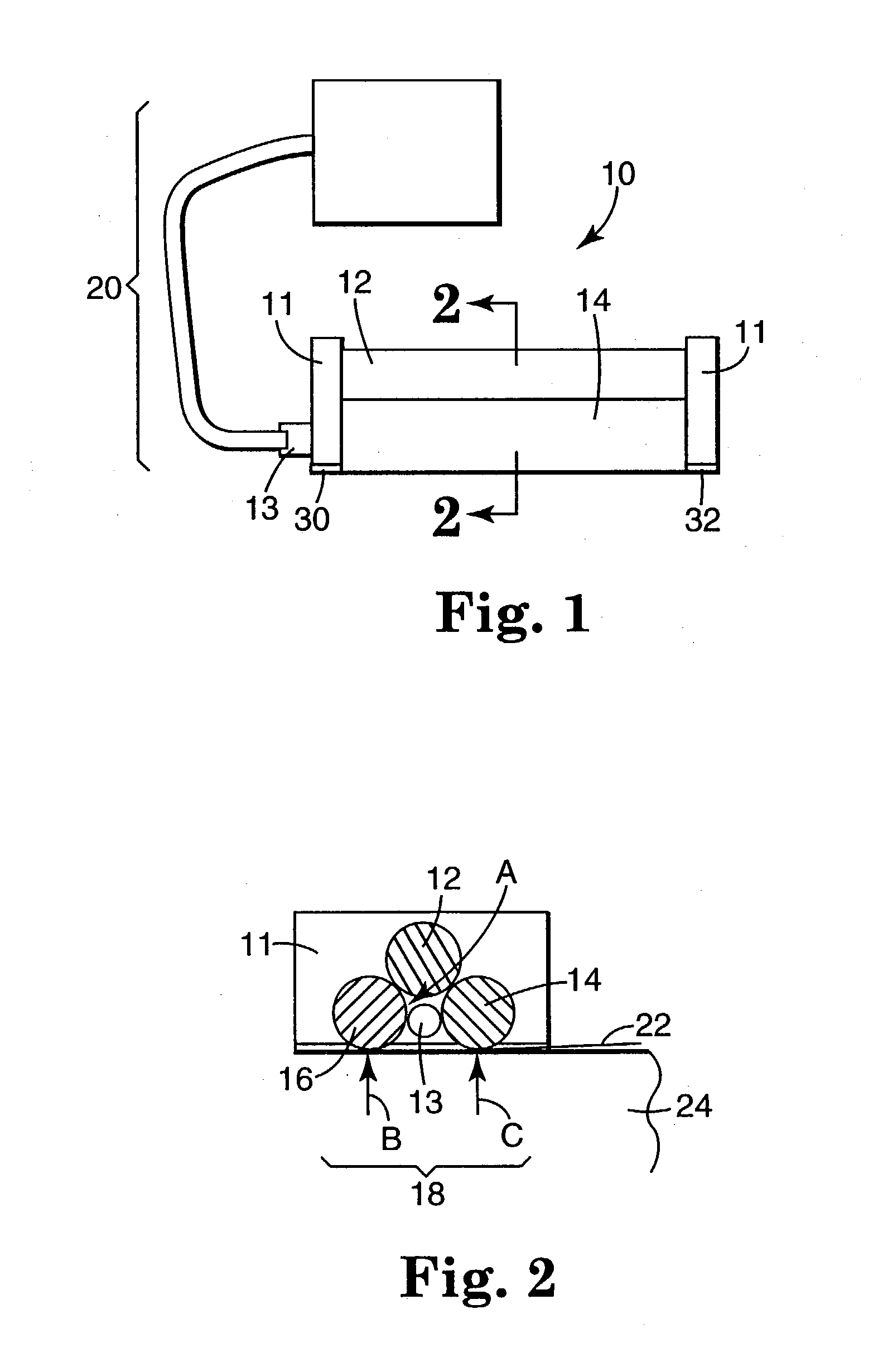
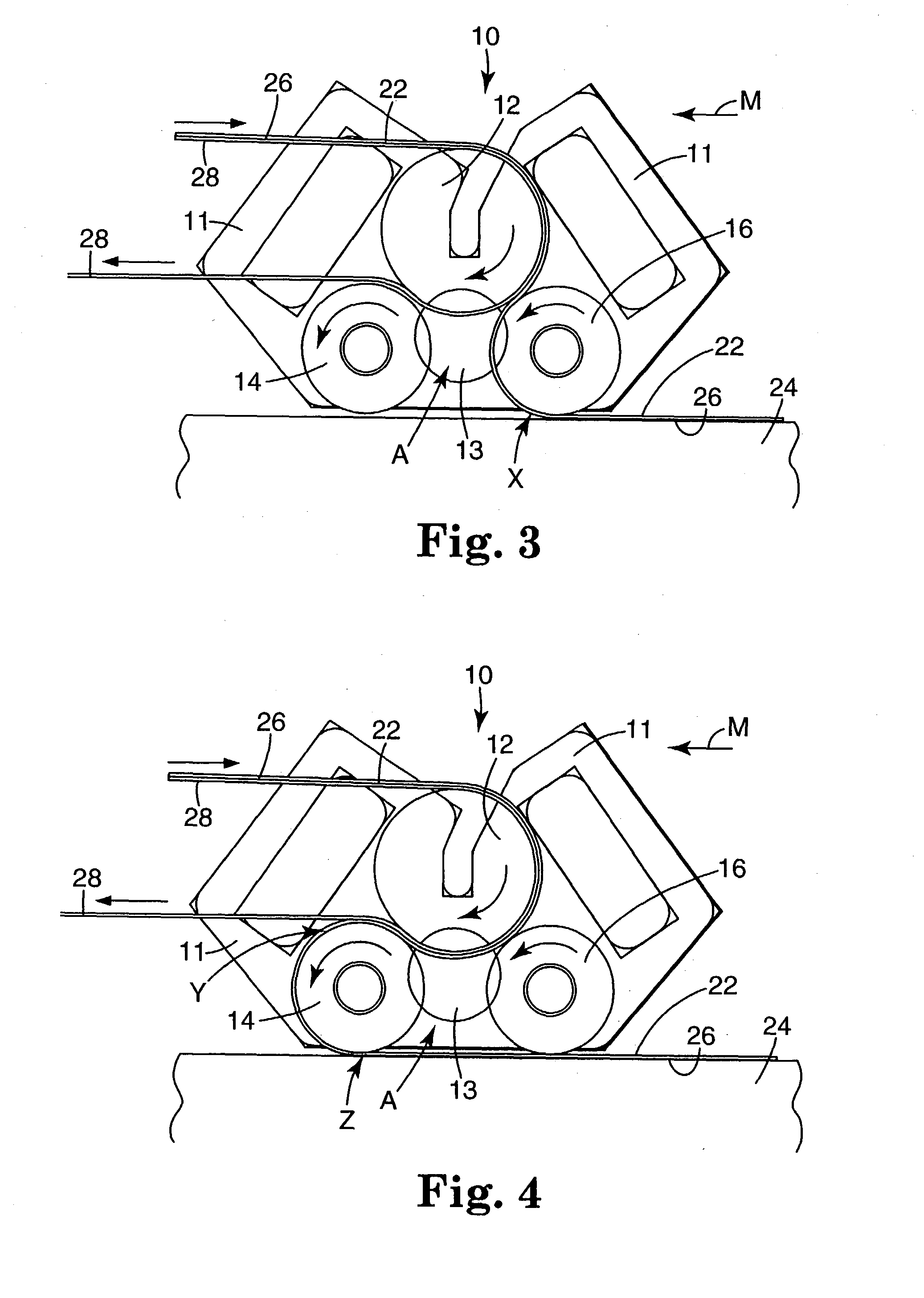
[0035] FIGS. 1 and 2 show one lamination apparatus 10 having a frame 11. At least one end of the frame 11 includes a vacuum port 13 in fluid communication with a vacuum cavity A formed in between the rolls 12, 14, and 16. The rolls 12, 14, and 16 combine to defined the vacuum cavity A and to provide lamination pressure on a film. The rolls 12, 14 and 16 are preferably circular and rotate about longitudinal axes extending through their centers. The longitudinal axes of the rolls are generally parallel to each other.
[0036] The lamination apparatus 10 may also include a vacuum or negative pressure source 20 that generates a partial vacuum (negative pressure) within the vacuum cavity A. That vacuum draws the outer rolls 14 and 16 against film 22 and the substrate 24 to provide the desired lamination pressure.
[0037] The substrate 24 on which the outer rolls 14 and 16 are mounted may be flat, or it may be curved such as, e.g., a roll. Furthermore, substrate 24 may be another film located ...
PUM
| Property | Measurement | Unit |
|---|---|---|
| Pressure | aaaaa | aaaaa |
| Depth | aaaaa | aaaaa |
| Vacuum | aaaaa | aaaaa |
Abstract
Description
Claims
Application Information
 - R&D
- Intellectual Property
- Life Sciences
- Materials
- Tech Scout
- Unparalleled Data Quality
- Higher Quality Content
- 60% Fewer Hallucinations
Browse by: Latest US Patents, China's latest patents, Technical Efficacy Thesaurus, Application Domain, Technology Topic, Popular Technical Reports.
© 2025 PatSnap. All rights reserved.Legal|Privacy policy|Modern Slavery Act Transparency Statement|Sitemap|About US| Contact US: help@patsnap.com


