Image output device, image forming device and method for generating video hard copy
a technology of image output device and image forming device, which is applied in the direction of digital output to print units, instruments, printing, etc., can solve the problems of response delay time and difficulty in us
- Summary
- Abstract
- Description
- Claims
- Application Information
AI Technical Summary
Benefits of technology
Problems solved by technology
Method used
Image
Examples
first embodiment
[0041] (The First Embodiment)
[0042] A video output device 10 according to the present embodiment captures image data of a video displayed on a television (hereafter, referred to as "TV") receiver and so forth and produces a hard copy based on the image data. Moreover, hereafter, "video" means moving images displayed on a monitor screen by TV broadcast, computer graphics and so forth.
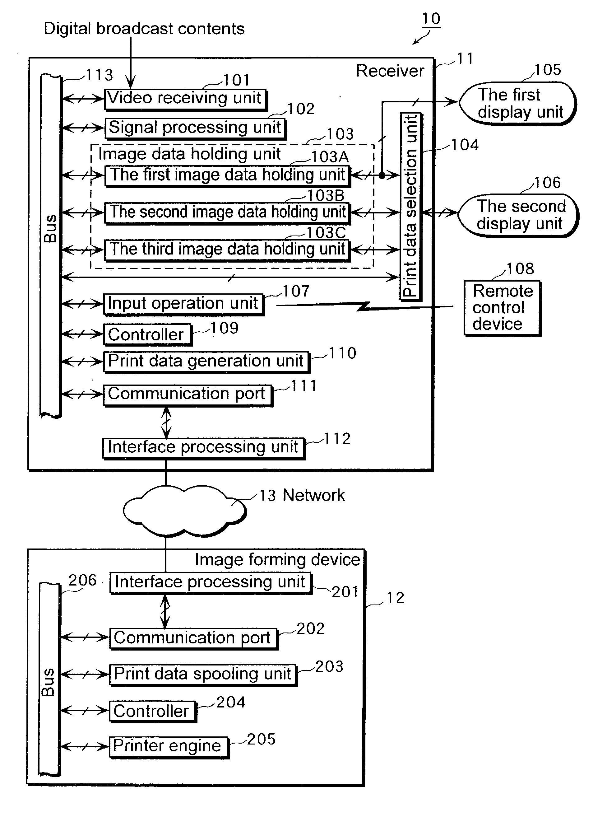
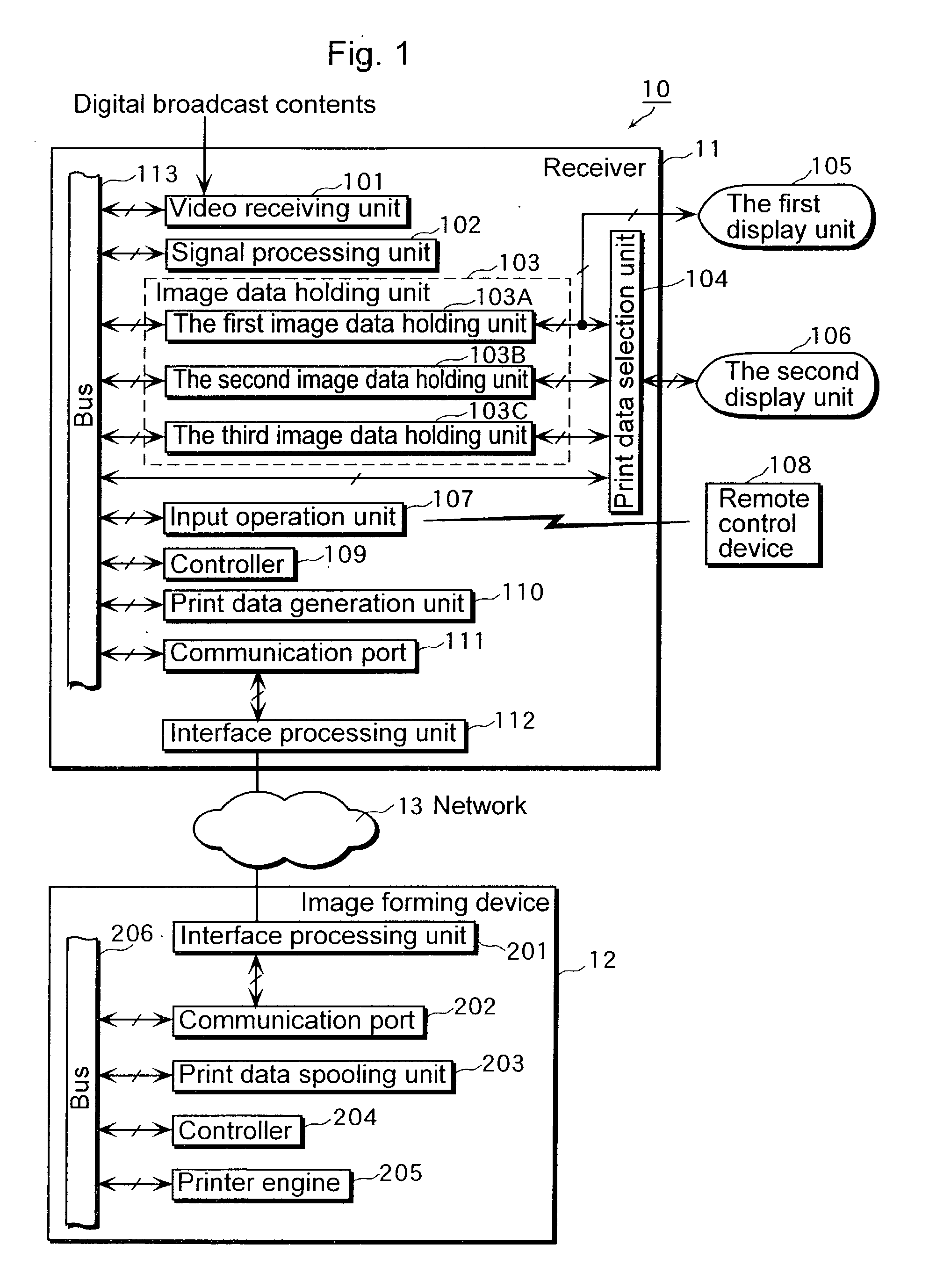
[0043] FIG. 1 is a block diagram that shows functional structures of a receiver 11 and an image forming device 12 that constitute the image output device 10.
[0044] The receiver 11 is a device that receives TV broadcast wave and so forth transmitted by terrestrial broadcasting, BS (Broadcasting Satellite), CS (Communication Satellite) and so forth, and comprises a video reception unit 101, a signal processing unit 102, an image data holding unit 103, a print data selection unit 104, the first display unit 105, the second display unit 106, an input operation unit 107, a remote control device 108, a control...
second embodiment
[0109] (The Second Embodiment)
[0110] In the first embodiment, a practical example in which the receiver includes the second display unit, the second and the third image data holding units is indicated, but in the second embodiment, a practical example in which the image forming device includes the second display unit, the second and the third image data holding units is indicated.
[0111] FIG. 7 is a block diagram that shows functional structures of a receiver 21 and a image forming device 22 that constitute an image output device 20 according to the second embodiment.
[0112] The different points between the structure shown in FIG. 7 and the structure shown in FIG. 1 are that, as is stated above, the receiver 21 according to the second embodiment does not include the second image data holding unit 103B, the third image data holding unit 103C, the print data selection unit 104, the second display unit 106 and the print data generation unit 110 in the receiver 11 according to the first e...
third embodiment
[0145] (The Third Embodiment)
[0146] In the third embodiment, operations of a remote control device to instruct printing according to the image output device 10 are explained referring to FIG. 9 and FIG. 10.
[0147] FIG. 9 is an external view of the remote control device 108 according to the present embodiment and FIG. 10 is a diagram that shows relationship between two frame images identified by receiving an instruction to print from the user and operations of the remote control device 108.
[0148] For a start, until the user pushes down a printing multiple button 601, the image data are continuously updated in the second image data holing unit 103B and the third image data holing unit 103C. This state is a state waiting for an input from the user 701.
[0149] Next, when the user pushes down the printing multiple button 601 once (let this time be the time T1 in FIG. 3), the update of the second image holding unit 103B and the third image holding unit 103C stops and two frame images are id...
PUM
 Abstract
Description
Claims
Application Information
 - R&D
- Intellectual Property
- Life Sciences
- Materials
- Tech Scout
- Unparalleled Data Quality
- Higher Quality Content
- 60% Fewer Hallucinations
Browse by: Latest US Patents, China's latest patents, Technical Efficacy Thesaurus, Application Domain, Technology Topic, Popular Technical Reports.
© 2025 PatSnap. All rights reserved.Legal|Privacy policy|Modern Slavery Act Transparency Statement|Sitemap|About US| Contact US: help@patsnap.com


