Tool, a machine, and a method for orbitally drilling an orifice
- Summary
- Abstract
- Description
- Claims
- Application Information
AI Technical Summary
Benefits of technology
Problems solved by technology
Method used
Image
Examples
Embodiment Construction
[0034] Below, the terms "front" and "rear" are used relative to the direction in which an orifice is drilled in a part, i.e. from the outside towards the inside of the orifice.
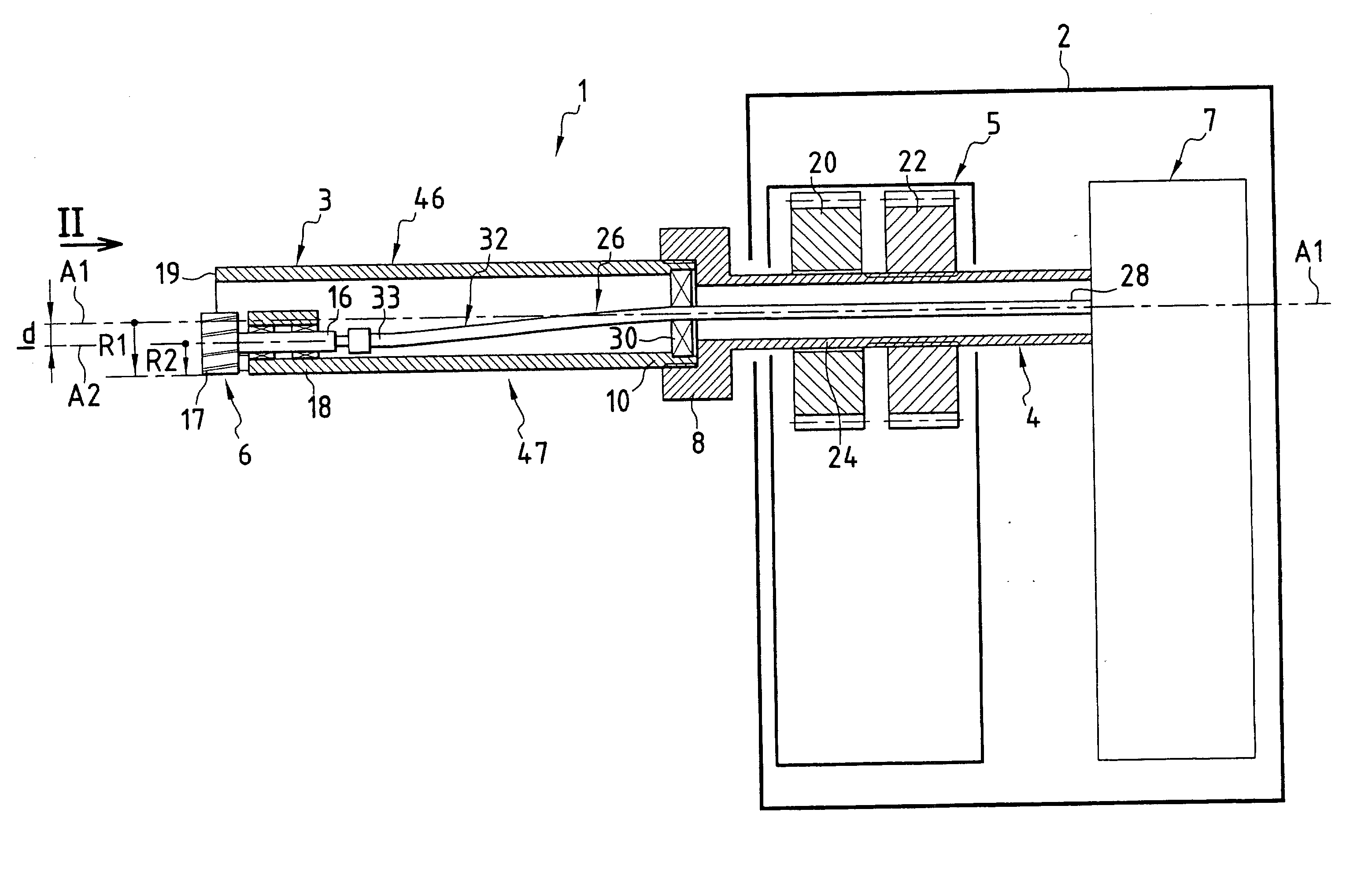
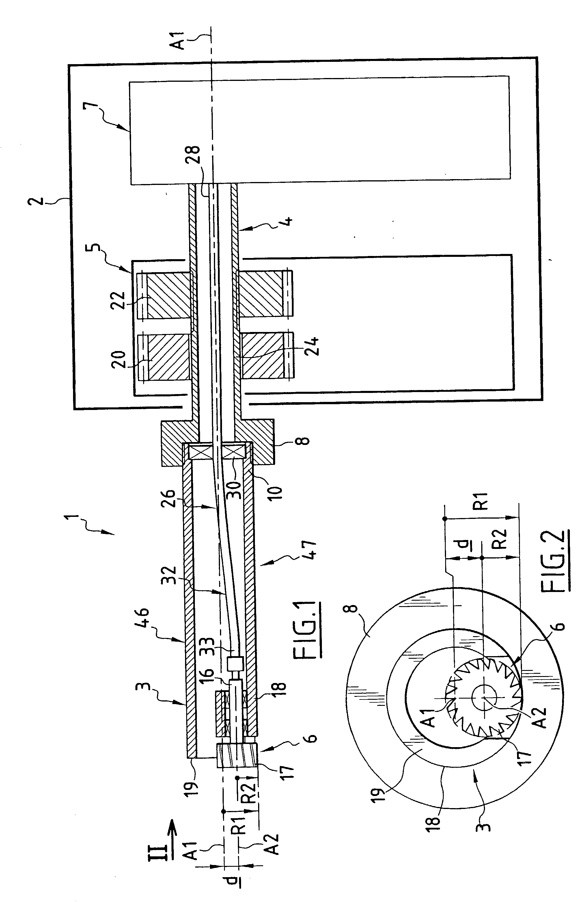
[0035] FIG. 1 is a diagram showing a drilling machine 1 for implementing an orbital drilling method.
[0036] The machine 1 mainly comprises:
[0037] a casing 2;
[0038] a cutter support 3 removably mounted on a spindle 4;
[0039] means 5 for driving the support 3, these means being housed in the casing 2;
[0040] a cutter 6 mounted on the support 3; and
[0041] means 7 for driving the cutter 6, these means being housed inside the casing 2.
[0042] The support 3 and the spindle 4 extend along a first axis A1 constituting a common central axis. The spindle 4 projects out from the casing 2 via a front or distal end 8, with the remainder of the spindle being received inside the casing 2.
[0043] The support 3 has its rear or proximal end 10 mounted at the front or distal end 8 of the spindle 4. The support 3 thus extends the spin...
PUM
| Property | Measurement | Unit |
|---|---|---|
| Radius | aaaaa | aaaaa |
Abstract
Description
Claims
Application Information
 - R&D Engineer
- R&D Manager
- IP Professional
- Industry Leading Data Capabilities
- Powerful AI technology
- Patent DNA Extraction
Browse by: Latest US Patents, China's latest patents, Technical Efficacy Thesaurus, Application Domain, Technology Topic, Popular Technical Reports.
© 2024 PatSnap. All rights reserved.Legal|Privacy policy|Modern Slavery Act Transparency Statement|Sitemap|About US| Contact US: help@patsnap.com


