
Electrophoretic displays using nanoparticles

a technology of electrotrophoretic displays and nanoparticles, applied in the direction of conductive pattern formation, input/output processes of data processing, metal pattern materials, etc., can solve the problems of long image quality, inadequate service life of these displays, and display can only produce two colors, so as to minimize parallax problems and control color saturation

Inactive Publication Date: 2003-05-22
E INK CORPORATION
View PDF0 Cites 113 Cited by
  • Summary
  • Abstract
  • Description
  • Claims
  • Application Information

AI Technical Summary

Benefits of technology

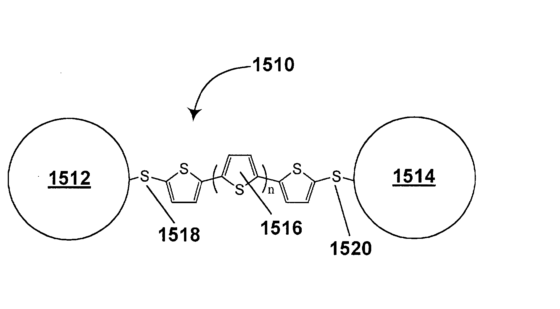
[0047] This invention also relates to a modification of the nanoparticle assemblies of type (b) discussed above, in which a plurality of nanoparticles are attached via tethers to a central particle. It has now been realized that if the central particle and the nanoparticles are given charges of opposite polarity, the tethers can be eliminated.
[0253] Core / shell nanoparticles used in the present invention may be formed by any known process for the formation of such composite particles. In the case of particles comprising a conductive shell around an insulating core, the generally preferred approach is to treat a suspension of the insulating cores, treated with a reagent which will bond to the conductive shell material, with a sol containing very small (1-2 nm) particles of this conductive shell material, thus causing these particles to bond to and "decorate" the core. Once a small amount of shell material has been placed on the core in this manner, the amount of shell material can be increased to any desired value by precipitating additional core material within a suspension containing the decorated cores, or by electroless deposition. See the aforementioned Oldenburg et al. paper. This type of process enables a consistent shell thickness to be obtained, and such consistent thickness is important since, as discussed in the aforementioned Oldenburg et al. paper, the absorption characteristics of the nanoparticles are greatly affected by the shell thickness.

Problems solved by technology

Such unencapsulated displays typically have problems with their long-term image quality which have prevented their widespread usage.
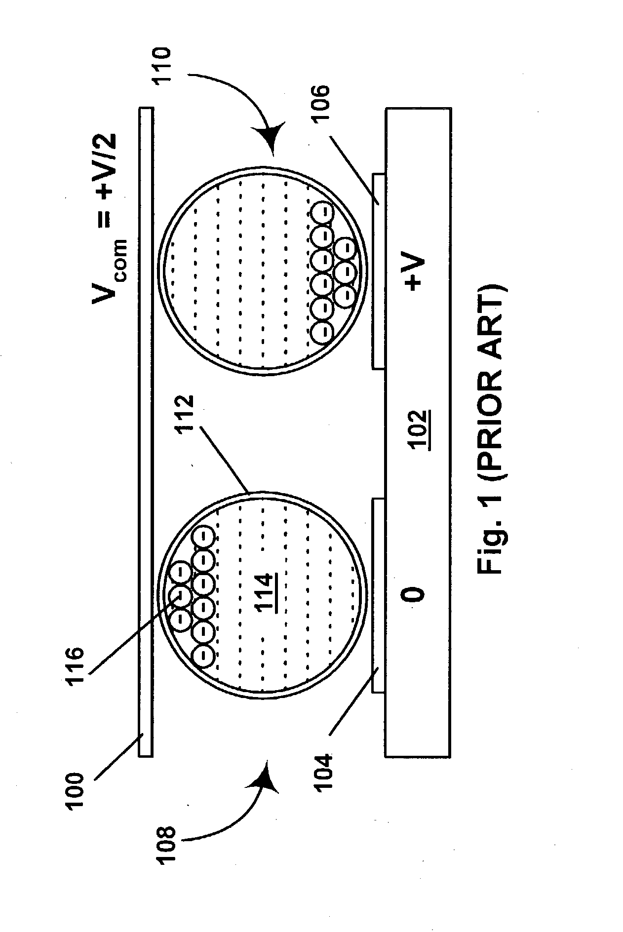
For example, particles that make up such electrophoretic displays tend to cluster and settle, resulting in inadequate service-life for these displays.
Firstly, the display can only produce two colors, in the manner already described, and is not capable of producing a wide range of colors.
Secondly, to effect a change between the two color states, it is necessary for the titania particles to move under the electric field essentially the full distance between the two electrodes, and in practice this typically leads to a transition time between the two states of a few hundred milliseconds, and a frame rate of the order of 1 Hz or less, which is too slow for video applications.
Such displays are not capable of producing a wide range of colors.
However, two obvious problems are likely to render such media containing more than three or four colors extremely difficult to produce in-practice.
This is a difficult challenge.
The main problem with this approach to generating color is that the brightness of the display is limited by the pixelation of the color filter.
For example, if a red color is desired, the pixels covered by red filters are set to appear red. whereas the pixels covered by green and blue filters are set to appear dark, so that only a fraction of the display surface has the desired color while the remaining portion is dark, thus limiting the brightness of any color obtained.
This design suffers from one of the same limitations as the display using color filters.
This limits the optical performance obtainable.

Method used


Image

  • Electrophoretic displays using nanoparticles
  • Electrophoretic displays using nanoparticles
  • Electrophoretic displays using nanoparticles

Examples


example 2

[0262] This Example illustrates a process of the invention for the synthesis of silver nanoparticles.

[0263] An aqueous silver nitrate solution (34.5 mL of a 0.036 M solution) were combined with a chloroform solution of tetrabutylammonium bromide (25.2 mL of a 0.39 M solution) and stirred for one hour. The organic phase was separated from the aqueous phase and hexanethiol (0.8 mL) was added. The resultant solution was stirred for one hour, sodium borohydride (27.5 mL of a 0.43 M aqueous solution) was added and the resultant mixture stirred for a further 12 hours. The resultant chloroform / silver nanoparticle phase was washed three times with ethanol to remove TBAB, excess hexanethiol and reaction products to produce a silver nanoparticle suspension useable directly in other processes of the present invention.

[0264] The present invention also provides additional processes for "driving" (i.e., bringing about the color change) in some of the types of nanoparticle-based display media desc...


PUM

PropertyMeasurementUnit
lengthaaaaaaaaaa
diameteraaaaaaaaaa
diameteraaaaaaaaaa

Abstract

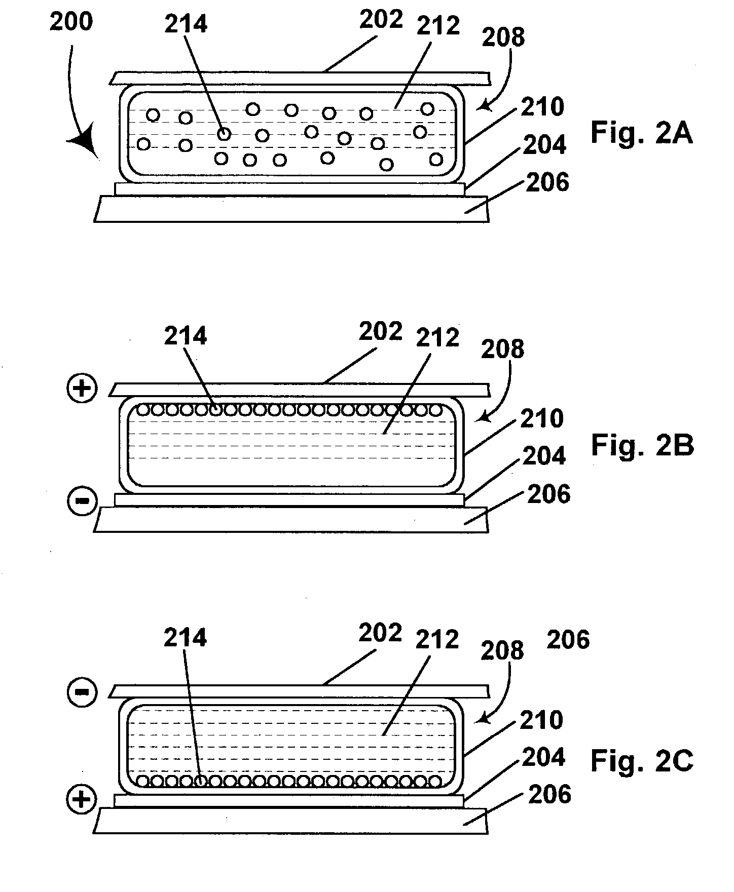
An electrophoretic display comprises a fluid and a plurality of nanoparticles having diameters substantially less the wavelengths of visible light such that, when the nanoparticles are in a dispersed state and uniformly dispersed throughout the fluid, the fluid presents a first optical characteristic, but when the nanoparticles are in an aggregated state in which they are gathered into aggregates substantially larger than the individual nanoparticles, the fluid presents a second optical characteristic different from the first optical characteristic. The electrophoretic display further comprises at least one electrode arranged to apply an electric field to the nanoparticle-containing fluid and thereby move the nanoparticles between their dispersed and aggregated states. Various compound particles comprising multiple nanoparticles, alone or in combination with larger objects, and processes for the preparation of such compound particles, are also described.

Description

[0001] This application is a continuation-in-part of application Ser. No. 10 / 054,721, filed Nov. 12, 2001 (published under No. 2002 / 0145792), which itself is a continuation-in-part of application Ser. No. 09 / 565,417, filed May 5, 2000 (now U.S. Pat. No. 6,323,989), which itself is a continuation-in-part of application Ser. No. 09 / 471,604, filed Dec. 23, 1999, which is a divisional of application Ser. No. 08 / 935,800 filed Sep. 23, 1997 (now U.S. Pat. No. 6,120,588). application Ser. No. 08 / 935,800 claims priority from Provisional Application Serial No. 60 / 035,622, filed Sep. 24, 1996, and is also a continuation-in-part of International Application No. PCT / US96 / 13469, filed Aug. 20, 1996, which itself claims priority from Provisional Application Serial No. 60 / 022,222, filed Jul. 19, 1996. application Ser. No. 09 / 565,417 also claims priority from Provisional Applications Serial Nos. 60 / 132,644 and 60 / 132,643, both filed May 5, 1999, and Provisional Application Serial No. 60 / 134,245, fi...

Claims


Application Information

Patent Timeline
Patent Type & Authority Applications(United States)
IPC IPC(8): B41J2/01B41J2/02B41J3/407C09D11/00G02B26/02G02F1/1333G02F1/1334G02F1/1343G02F1/1347G02F1/167G04B47/00G04G21/04G06F3/14G06F3/147G09F9/37H05K1/09H05K3/10H05K3/12H10K99/00
CPCB41J2/01Y10T428/25B41J3/4076B82Y20/00C09D11/30C09D11/50G02B26/026G02F1/133305G02F1/13336G02F1/1334G02F1/13439G02F1/1347G02F1/167G02F1/19G02F2201/16G02F2201/44G02F2202/28G02F2202/36G04B47/00G09F9/372H01L51/005H01L51/0077H01L51/0508H01L51/0512H05K1/097H05K3/105H05K3/1241Y10T428/294B41J2/02H10K85/60H10K85/30H10K10/46H10K10/462
Inventor JACOBSON, JOSEPH M.PULLEN, ANTHONY E.WHITESIDES, THOMAS H.DRZAIC, PAUL S.MORRISON, IAN D.WANG, JIANNAGRAY, CAPRICE L.
Owner E INK CORPORATION
Learn More